TR515 User’s Manual
16
operation in the Test mode are provided in Section 6. Note, that Test mode
destroys database memory contents in such a way that the data cannot be
recovered even with the M-command.
.
4. Registers
The TR515 features a number of programmable “registers”. Basically,
registers are the TR515’s functioning parameters (Settings). Registers can be
written to using the C-command, and read from using the B-command (see
Section 3 for details).
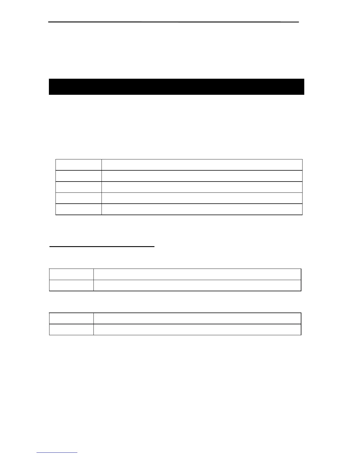
Table below lists all available registers:
00H LED display mode (0: wall-mount, 1:desktop)
01H Bell duration in seconds (00H-FFH)
02H-21H Bell table, times (total of 32 registers)
22H-41H Bell table, enable/disable (total of 32 registers)
42H Event selection mode, free (IN or OUT)/IN only/OUT only
LED display mode (register 00)
Set
Possible error codes: 04, 07
Command C00,
MM
Reply A
Get
Possible error codes: 04, 07
Command B00
Reply A
MMcc
MM
- display mode (00: wall-mount operation, 01: desktop operation),
cc
-
checksum
This register is used to set the LED display mode. Because TR515 can be
used both as a wall-mount and as a desktop device, the LED data must be
displayed in either orientation. Setting register to 00 (default) adjusts LED
picture for wall-mount operation. Setting the register to 01 rotates the image so
that it appears correctly when operating as a desktop device. Note: the mode