6
Setup and operation
11
Installation
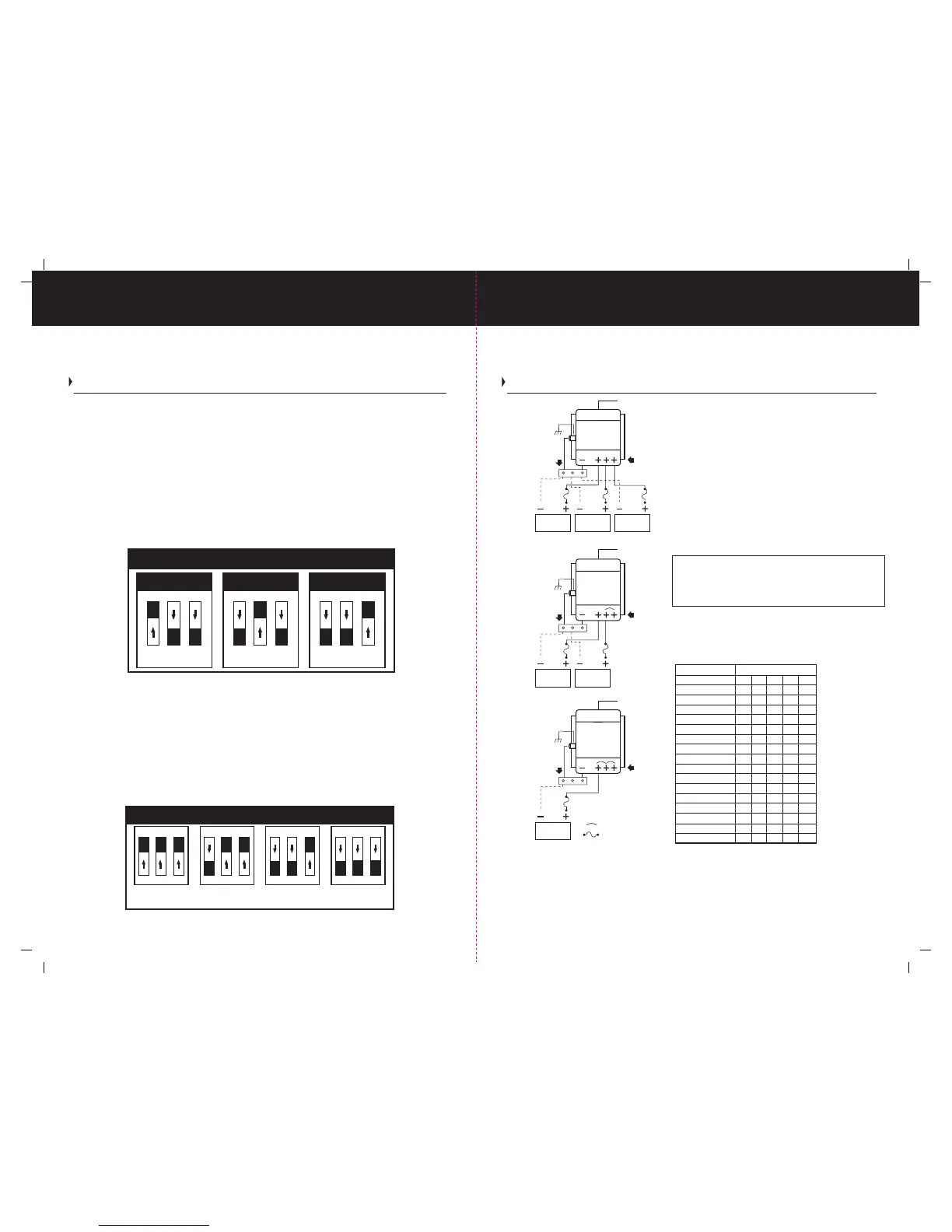
Typical 12 Volt DC Common Ground Installation Wiring Diagrams
(ABOVE) It is recommended that a jumper(s) be used between unused positive DC output
post(s) and a used positive DC post connected on your ProTech-i Series Charger. Please note
you can connect all three positive DC output posts together to form a single DC output on
your ProTech-i Series Charger.
All installations should be made in compliance with ABYC E-11 specifications for AC and DC
electrical systems on boats and specifications for A-31 Battery Chargers and inverters.
Setup and Operation Continued
Programmable Battery Type Selector Switch
Your battery charger has a user programmable battery type selector switch that is factory
set for Flooded (Lead-acid) battery(s). Please confirm the appropriate battery type and the
orientation of selector switch before use.
In order to change the factory setting from Flooded (Lead-acid) to either AGM or GEL type
batteries, simply, remove AC power to the battery charger, remove the end cap cover on the
DC end of the charger and locate the user programmable battery selector switch. Shown below
you will find the three battery type configuration settings that are used to program the 3 position
dip switch as shown below. Choose the correct one for your battery type. If you are unsure as
to what kind of battery you have please refer to “Selecting a Charging Profile & Understanding
Battery Types” on page 7. Once your ProTech-i is programmed for your battery type, reinstall
DC endcap. Apply AC power. The Battery Type LED will illuminate indicating your selection.
Note: If more than 1 battery type is illuminated, recheck your battery type selector switch
positions as illustrated above. It should be noted, only (1) of the 3 switch tabs located on
top of the 3 tab dip switch can be in the "ON" position for proper selection and operation.
Programmable Absorption Timer Switch
The ProTech-i Series is equipped with a programmable absorption timer switch that places the
charger into the absorption / conditioning mode for a period of 1,2,3 or 4 hours as programmed
and indicated by the switch selection. Determine the best absorption / conditioning time either
by obtaining your battery manufacturers recommended specifications or by using the guidlines
on page 7. Below are the 1,2,3 and 4 hour switch configuration settings that are used to program
the 3 position dip switch to the desired length of time.
12 Volt 10 Amp Length Out and Back
Wire length 10' 15' 20' 25' 30'
AWG 14 12 10 10 10
12 Volt 15 Amp
Wire length 10' 15' 20' 25' 30'
AWG 12 10 10 8 8
12 Volt 20 Amp
Wire length 10' 15' 20' 25' 30'
AWG 10 10 8 6 6
12 Volt 25 & 30 Amp
Wire length 10' 15' 20' 25' 30'
AWG 10 8 6 6 4
12 Volt 40 Amp
Wire length 10' 15' 20' 25' 30'
AWG 8 6 6 4 4
24 Volt 20 Amp
Wire length 10' 15' 20' 25' 30'
AWG 14 12 10 10 10
Three Bank / 12 Volt DC Installation (FIG.1)
Connect DC cables to three of the positive DC output
posts as shown. Connect common ground negative
wire (as described below)
Two Bank / 12 Volt DC Installation (FIG.2)
Connect DC cables to two of the positive DC output
posts and use one jumper wire to connect the unused
post. Connect common ground negative wire (as
described below)
One Bank / 12 Volt DC Installation (FIG.3)
Connect to one positive DC output post and use two
jumpers to connect to the remaining unused posts. Connect
common ground negative wire (as described below)
Battery negative wires are installed separately to
the boat’s DC Negative / Ground buss bar (not provided).
Then a single connection is made to the charger. Note:
See page 13 for DC Chassis Ground connection details.
Table No.1 Wire gauges by amp rating and total
out and back wire distance as defined by the
length of the positive wire which must be added
to the length of the return negative wire.
Absorption Time Selector Switch
1 2 3
ON
1 Hour
Absorption
1 2 3
ON
2 Hour
Absorption
1 2 3
ON
3 Hour
Absorption
1 2 3
ON
4 Hour
Absorption
Indicates Jumper Wire
Indicates a Fuse
Note:
bank 1 bank 2 bank 3
AC Input
DC Outputs
Common Negative
FIG.1
DC Chassis Ground
ProTech-i
bank 1 bank 2
AC Input
DC Outputs
Common Negative
FIG.2
DC Chassis Ground
bank 1
AC Input
DC Outputs
Common Negative
FIG.3
DC Chassis Ground
ProTech-i
ProTech-i
Battery Type Selector (Switch Positions)
1 2 3
ON
OFF
Flooded
(Lead Acid)
1 2 3
ON
OFF
AGM
(Absorbed Glass Mat)
1 2 3
ON
OFF
GEL
(Gelled Electrolyte Lead-acid)
SW 2
SW 1