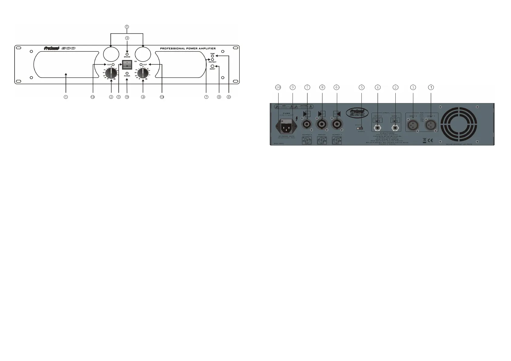
9. Bridge LED. This LED illuminates to show that mono bridge mode has been selected on the rear
panel. Channel A level only is active, and speaker loads should be connected for bridge mode
operation as described below.
10. Clip LED (one per channel). This illuminates when the input signal is clipping, or within 3dB of
clipping. In normal use this should illuminate briefly only on signal peaks. If it illuminates constantly,
or most of the time reduce the input signal level.
11. Power LED. This illuminates to show the amplifier is connected to AC power and switched on. When
the amplifier is switched off this will slowly dim and extinguish.
Rear panel features
1. Channel A XLR input socket. This accepts line level balanced or unbalanced signal. Use this input for
Channel A in stereo mode, or for mono bridge mode operation.
2. Channel A TRS jack input socket. This accepts line level balanced or unbalanced signal. Use this
input for Channel A in stereo mode, or for mono bridge mode operation.
3. Channel B XLR input socket. This accepts line level balanced or unbalanced signal. Use this input for
Channel B in stereo mode. This input is not used in bridge mode.
4. Channel B TRS jack input socket. This accepts line level balanced or unbalanced signal. Use this
input for Channel B in stereo mode. This input is not used in bridge mode.
NOTE ; Always use good quality shielded cables for all signal connections. Keep signal cables away
from speaker cables, AC power cables or other high current carrying cables.
5. Mode switch. This switch can be set to Stereo (Channel A and channel B active and independent) or
Bridge (amplifier works as a single mono amplifier) mode.
6. Channel A speaker output socket (Speakon). Connect speakers with a total impedance of not less
than 4 ohms to this socket when in stereo mode only. The output level is controlled by the Channel A
volume control on the front panel
7. Channel B speaker output socket (Speakon). Connect speakers with a total impedance of not less
than 4 ohms to this socket when in stereo mode only. The output level is controlled by the Channel B
volume control on the front panel
8. Bridge mode speaker output socket. Connect speakers with a total impedance of not less than 8 ohms
to this socket when in bridge mode only. The output level is controlled by the Channel A volume
control on the front panel.
NOTE ; Use low resistance, unshielded high power speaker cables to connect the amplifier to your
speakers. Keep the cables as short as is practical, and keep them away from the input signal cables
- 5 -
OPERATION
Front panel features
1. Exhaust vent. This vent must be kept free from obstruction, to allow hot air drawn through the amplifier
to exit. During use warm air will blow from this vent.
2. Channel A level (volume) control. In stereo mode operation this controls the amplifiers power output on
Channel A. In bridge mode this controls the amplifiers bridged output. We recommend setting this to
maximum during use to give best headroom and dynamics. Overall level should be controlled from your
mixer or audio source.
3. Power switch. This switch turns the amplifier on. When switched to ‘OFF’, the internal circuit is isolated
from the AC supply.
4. Channel B level (volume) control. In stereo mode operation this controls the amplifiers power output on
Channel B. In bridge mode this control is inactive and should be set to zero. We recommend setting this
to maximum during stereo operation to give best headroom and dynamics. Overall level should be
controlled from your mixer or audio source.
5. VU meter (one per channel). This meter shows the level of input signal, and will fluctuate during use with
signal level. The output level of your mixer or audio source should be set so that the needle swings into
the red zone only on signal peaks. If the needle is usually in the red zone, the input level should be
reduced at the source to prevent distortion and overheating.
6. Reset button. If the amplifier output is short circuited, or a low load impedance is connected, the ‘Protect’
LED (7) will illuminate and amplifier output will be shut down. If this happens, check that the outputs are
properly connected to a suitable load, using good quality, undamaged cables. Turn the volume controls
to zero, and press the reset button. The amplifier should return to normal operation.
NOTE ; If the amplifier keeps returning to protect mode, check all connections and speaker impedances.
If the amplifier will not operate when correctly connected to a suitable load contact a qualified Service
Engineer. DO NOT attempt to hold the reset button in to defeat the protection. Serious damage could
occur.
7. Protect LED. When this LED illuminates, the onboard protection has cut in, disabling the amplifier to
protect it from fault conditions. If this illuminates, turn the amplifier off and check all connections and load
impedance.
8. TEMP LED. When this LED illuminates, the onboard over temperature protection has cut in, disabling
the amplifier to protect it. This will occur if insufficient ventilation is available, or the amp is being
overdriven. If this illuminates, turn the level controls to miniumum and check ventilation to front and rear.
The amplifier will return to active mode after a few minutes to cool down. When restarting the amplifier,
check the input signal levels using the VU meters, as described in 5 above.
- 4 -
 Loading...