16
Rev. D / January 2015
CVM-780 Contact Voltmeter
1. A 20pF is placed on a ground plane and a high impedance contact voltage probe connected to
its charging conductor.
2. The capacitor is charged to a dened voltage using a precision DC voltage supply.
3. The CVM-780 under test is grounded and its probe zeroed.
4. The capacitor’s charged conductor is measured with the CVM-780 under test.
5. The CVM-780’s measurement deviaon from the (a) inial capacitor’s reference voltage before
contact by the CVM under test and (b) the installed voltage monitor aer test are recorded.
6. The data is then used to calculate the capacitor’s voltage change due to the measurement and
any deviaon seen between the installed reference instrument and the unit under test.
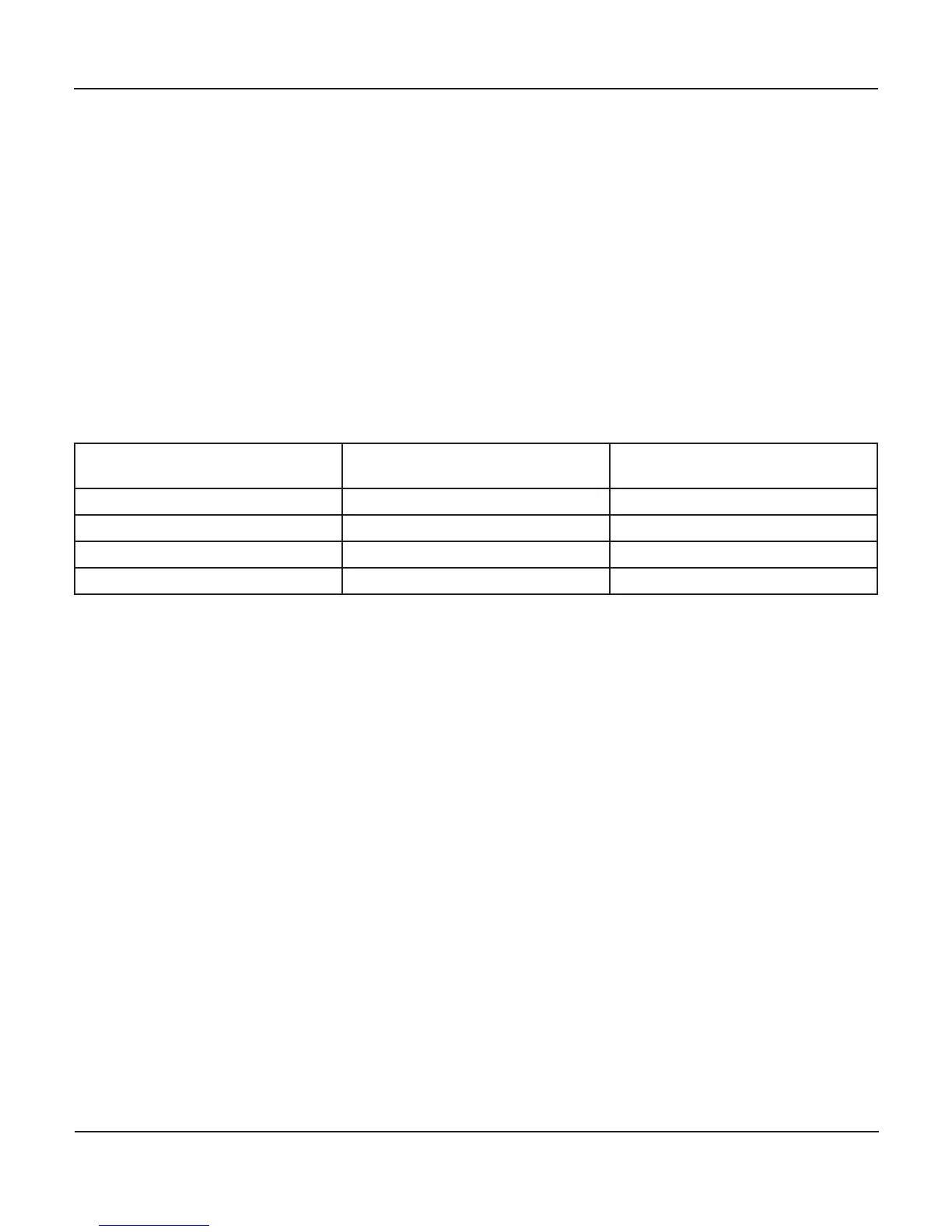
Typical measurement deviaon is summarized below.
-
1C 450 - 525 V <±5% ±2 Counts ≤ ±2 Volts
2C 75 - 150 V <±5% ±2 Counts ≤ ±2 Volts
3C 40 - 65 V <±5% ±2 Counts ≤ ±2 Volts
4C <25 V <±10% ±2 Counts ≤ ±2 Volts
In the Performance Measurements table, above, the % DEV. FROM INITIAL CAPACITOR VOLTAGE is the to-
tal voltage change of the charged, monitored capacitor when the CVM under test makes contact with the
reference capacitor’s conductor. At the moment of contact by the CVM under test, the reference capacitor
system voltage changes slightly. The percent change from the capacitor’s inial voltage is based on a com-
binaon of two elements (a) the addional capacitance of the probe assembly p to that of the oang
capacitor and (b) some inevitable electron transfer between the capacitor conductor and the probe p.
The instrument monitoring the capacitor and the CVM-780 under test are both high impedance contact
voltmeters with very low capacive loading on the measurement. Consequently, if well zeroed and prop-
erly grounded they should each measure the same voltage on the capacitor aer contact of the CVM-780.
under test. Any error would be that of operator zero adjustment and ground anomalies. Thus a 2 volt or
less dierence between the two voltmeters would be considered acceptable.
Note that the precision reference capacitor is used to conrm CVM-780 performance by providing a stable
voltage plaorm. The use of charge plate monitors in CVM-780 performance tesng is avoided because
(a) while total CPM capacitance changes at the moment of probe contact, (b) total CPM capacitance var-
ies dramacally with its design and surroundings, including the operator and other moving objects in the
vicinity. Using a reference capacitor minimizes these measurement variables.
Thus, in real world the accuracy of praccal CVM-780 measurements of a conducve object are based on:
• The object’s capacitance and charge in combinaon with
• The probe assembly’s capacitance
• Ambient condions
• Process dynamics
• The small transfer of electrons between the probe p and the object under test