Q45 2
PROTECO S.r.l.
Via Neive, 77 - 12050 Castagnito (CN) ITALY Tel. +39 0173 210111 - Fax +39 0173 210199 info@proteco.net - www.proteco.net
TR3
K2
K3
F2
RL1
JP4
JP3 JP1
P1 P2 P3
J3
F1
SET WORK BREAK
5A-250V
1 2 3 4 5 6 7 8 9 10 11 12 13 14 15 16
DL1
SW1
CAPACITOR
NEUTRAL
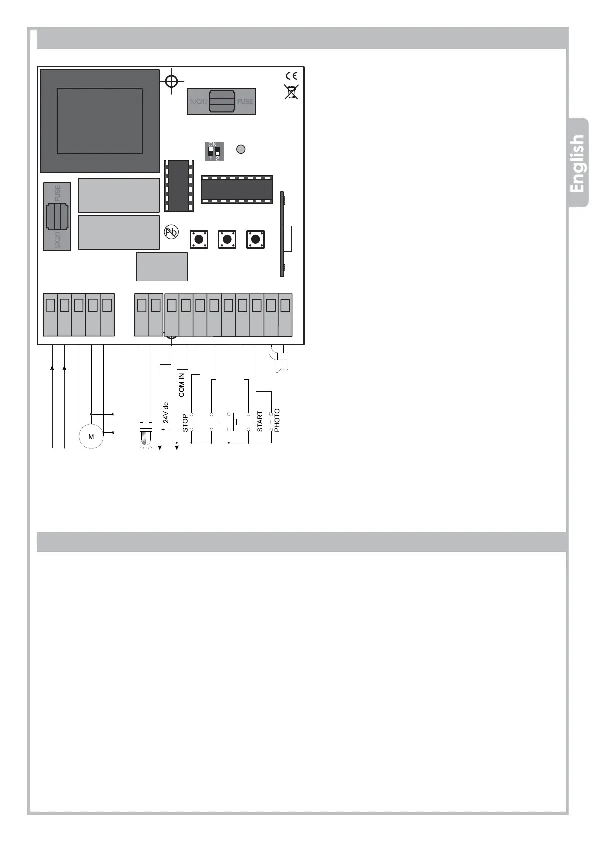
Main components description
F1 = Accessories protection fuse 24V, 1.6A
F2 = Main power and motor protection fuse 230V, 5A
J3 = Radio receiver
DL1 = Control panel’s status LED
SW1 = Programming dip-switches block
SET = Control panel Programming key
WORK = Working time adjustment key
BREAK = Pause time setting key for automatic closing
2. WIRING DIAGRAM
Polarity in main power supply line connection
must always be respected
(plug 1= Neutral, plug 2 = Phase).
Minimum wire-section size for 230Vac outputs
(motors and light) is 1.5mm²
Always use separate wires for accessories and
controls wiring (24V) to avoid disturbances or
damages caused by synchronous generated
voltage. Do not use only one multi-core cable
for wiring.
In case of wirings longer then 50m, we recom-
mend to decouple the command circuits by
using suitable relays on main electric board.
2. ELECTRIC WIRINGS
1 - 2 = MAIN POWER 230Vac ~ 50Hz
1 Neutral
2 Line
6 - 7 = FLASHING LIGHT. Blinking signal
FLASH 24Vac, max 10W
3 - 4 - 5 = MOTOR output. Max 700W.
3 Neutral
4 Open
5 Close
8 - 9 = PHOTOCELLS output 24Vdc. Max 500 mA
8 Positive
2 Negative
9 - 10 = STOP command (NC contact).
STOP Always stops the motor.
If the stop command is given during the
pause time, automatic closing will be
disabled.
9 – 11 = CLOSING command (NO contact).
9 – 12 = OPENING command (NO contact).
9 – 13 = START command (NO contact).
Step-by-step mode (open, stop, close)
9 – 14 = CLOSING PHOTOCELL input (NC contact).
Active only when closing
(stops and reopens).
15 - 16 = AERIAL terminal block
15 aerial EARTH
16 aerial SIGNAL
9 – 13 = CLOCK Timer input (NO contact).
To enable pre-set open/close timing
CLOSING
OPENING
BLINKING
LINE
NEUTRAL
CLOSING
OPENING
SIGNAL wire
EARTH wire
 Loading...