EasyManua.ls Logo

Proteco myGate Q81A User Manual

Proteco myGate Q81A
21 pages
To Next Page IconTo Next Page
Page #1 background imageLoading...
Page #1 background image
Q81A
05_2021
CONTROL PANEL FOR
DOUBLE/SINGLE SWING GATES
Control panel for 230V ac operators – single and double leaf swing gates
Automatic programming mode with obstacle detection
Sequential programming mode: adjustable force, slow down, working time per single motor
Immediate closing
Pedestrian opening
Multi-occupation feature
Second radio channel interface (optional)
Output for electrolock connection
Ram blow and lock pulse function
Removable radio receiver 433,92 MHz (32 codes) suitable for fixed or rolling code transmitters
Input for 8K2 resistive safety edge
Self diagnosis of malfunctions by LED coding
230V ac
TECHNICAL FEATURES
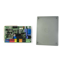
Item code PQ81A, PQ81A1D
Pcb’s dimensions 137 x 84 x 37 mm
Junction box dimensions 220 x 290 x 90 mm
Pcb’s weight 160 g
Main Power supply 230V, 50-60 Hz
Power supply Tolerance -10% +20%
Transformer 230/21Vac – 15VA
Main Fuse 5 A
Rated power 600 W
Max. power draw 3.5 A
Power draw in stand-by 30 mA
Blinker 24 Vac, max 20 W
Accessories 24 Vdc , max 5 W
Electrolock 12 Vdc, max 15 W
Operating temperature -20 +50 °C
Protection rating IP55
Instructions Manual
PROTECO S.r.l. Via Neive, 77 - 12050 Castagnito (CN) ITALY Tel. +39 0173 210111 - Fax +39 0173 210199 info@proteco.net - www.proteco.net

Questions and Answers:

Proteco myGate Q81A Specifications

General IconGeneral
BrandProteco
ModelmyGate Q81A
CategoryControl Panel
Power supply230 Vac
Operating temperature-20°C to +55°C
Protection classIP54

Summary

1. SAFETY INSTRUCTIONS AND PRELIMINARY CHECKS

2. DESCRIPTION AND MAIN COMPONENTS

3. ELECTRICAL CONNECTIONS

3.1 MOTORS WIRING

Details the wiring process for motors in various gate automation models.

3.2 MAIN POWER

Instructions for connecting the main power supply to the control panel.

3.3 START DEVICES

Wiring instructions for start commands, including timers and key switches.

3.4 PEDESTRIAN OPENING

Guidance on wiring the pedestrian opening function for gate control.

3.5 EMERGENCY STOP BUTTON

How to wire the emergency stop button for safety compliance.

3.6 PHOTOCELLS

Wiring instructions for photocell safety sensors in closing and opening.

3.7 SAFETY EDGE

Instructions for connecting safety edges for obstacle detection.

3.8 FLASHING LIGHT

Wiring the flashing light accessory for visual signaling.

3.9 ELECTROLOCK

Instructions for connecting the electrolock for enhanced gate security.

4. DEFAULT SETTINGS

5. BROWSING THE MENU

5.1 FUNCTIONS MENU

Overview of the control panel's function menu and available settings.

6. OPERATION MODE

7. RADIO CODES

7.1 DELETING EXISTING RADIO CODES

Procedure for removing all stored remote control codes from the system.

7.2 LOADING A REMOTE CONTROL AS START COMMAND

How to program a remote control for the gate's start command.

7.3 LOADING A REMOTE CONTROL AS PEDESTRIAN COMMAND

Procedure to store a remote control for the pedestrian opening function.

7.4 LOADING A REMOTE CONTROL AS 2° RADIO CHANNEL COMMAND (MRX01 jack)

Instructions for programming a remote for the second radio channel.

8. PROGRAMMING

8.1 AUTOMATIC mode

Details on setting up automatic operating modes with obstacle detection.

9. TROUBLE SHOOTING – ERROR MESSAGES

Related product manuals