TR AS
+
+AC
-AC
TX
+
-
RX
+AC -AC
24
12Vdc
24Vac
24Vdc
12Vdc
24Vdc
24Vca
JP4 JP5 JP6
1 2 3 4 5 6 7 8 9 10 11
TR AS
+
+AC
-AC
TX
+
-
RX
+AC -AC
24
12Vdc
24Vac
24Vdc
12Vdc
24Vdc
24Vca
JP4 JP5 JP6
1 2 3 4 5 6 7 8 9 10 11
JP4
JP5
JP6
JP4
JP5
JP6
Q81A_5_2021 7
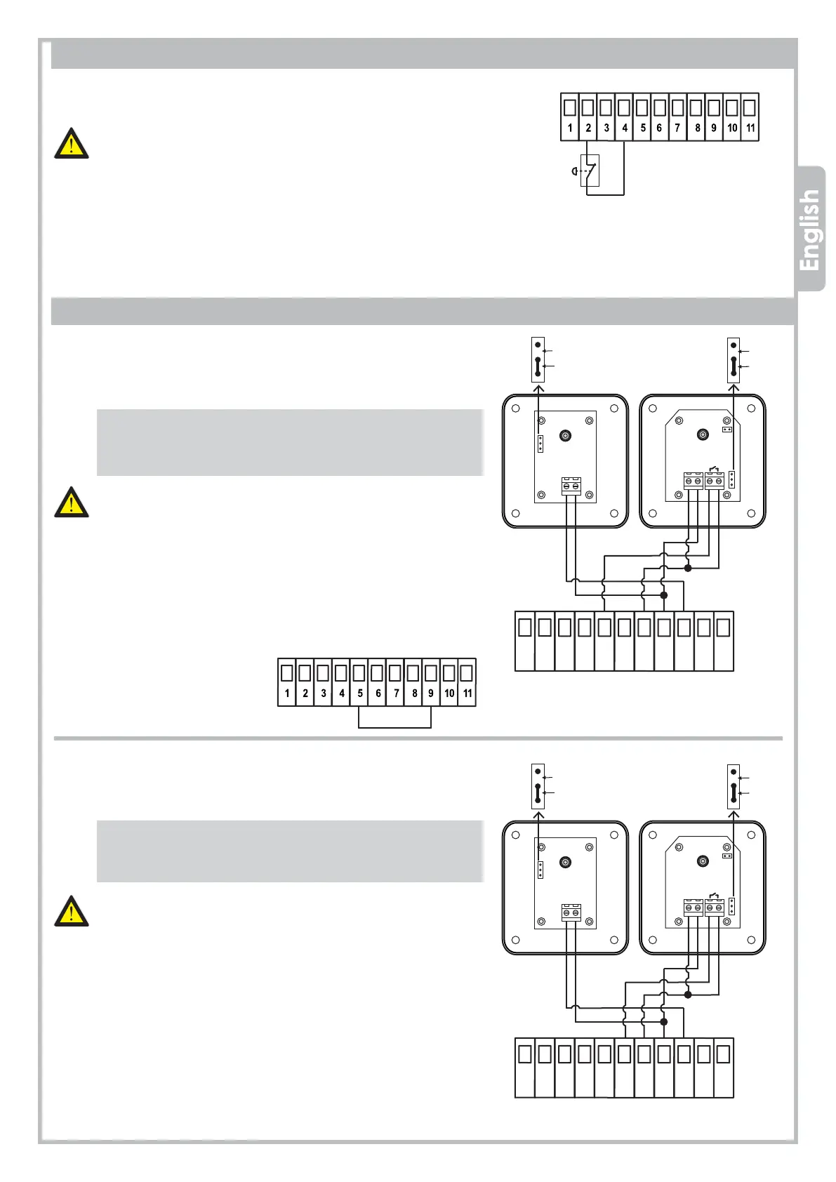
3.6 PHOTOCELLS
3.6.1 Photocells IN CLOSING
Feed the photocells through 7-8-9, terminal JP5.
Wire the photocell contact (N.C. contact) to 5-7, terminal JP5.
An additional photocell set can be wired in SERIES (N.C. contact).
• If the photocell beam is broken during CLOSING, the gate
stops and reverses after 1,5 sec.
• If the photocell beam is broken during OPENING, the gate
keeps on working normally.
The PHOTOCELLS IN CLOSING are important for the safety
of people and objects.
N.B.: To desable the photocell in closing during installation,
plug 5 and 9 together.
3.6.2 Photocells in OPENING
Feed the photocells through 7-8-9, terminal JP5.
Wire the photocell contact (N.C. contact) to 6-7, terminal JP5.
An additional photocell set can be wired in SERIES (N.C. contact).
• If the photocell beam is broken during OPENING, the gate
stops temporarily.
• When the photocell beam is free, the gate goes to normal
operation.
The PHOTOCELLS IN OPENING are important for the safety
of people and objects.
Nota: Before wiring any PHOTOCELL in OPENING, remove
the jumper between terminal 6 and terminal 9.
3.5 EMERGENCY STOP BUTTON
Wire the STOP BUTTON (N.C. contact) to 2 - 4, terminal JP4.
An additional STOP BUTTON contact can be wired in SERIES (N.C. contact).
The EMERGENCY STOP BUTTON is important for the safety
of people and objects
N.B.: To desable the STOP BUTTON during installation,
plug 2 and 4 together.
Note: Before wiring any STOP contact remove the jumper between
terminal 2 and terminal 4.
PLUG 5 AND 9
EMERGENCY
STOP BUTTON
PROTECO S.r.l.
Via Neive, 77 - 12050 Castagnito (CN) ITALY Tel. +39 0173 210111 - Fax +39 0173 210199 info@proteco.net - www.proteco.net
 Loading...