J5
JP6
FLASH
24V ac
max 20 W
J5
24Vac
230Vac
J5
JP2 JP3
TR2
DL2
- + - +
SENS POWER
K4
C26
C27
K2
K3
- + - +
OP2
V1
FR1
SET SET TX
WORK BREAK
21 22
SW1 SW2
DL1 DL8
U2
1 2 3 4
ON ECE
24Vac
230Vac
J5
JP3
JP8
JP9
1 2 3 4 5 6 7 8 9 10 11 12 13 14 15 16 17 18 19 20
JP1
JP2 JP3
TR2
C21
C24
POWER
230Vac
5A
230Vac
DL2
- + - +
SENS POWER
K4
C26
C27
K2
K3
- + - +
OP2
V1
FR1
SET SET TX
WORK BREAK
21 22
SW1 SW2
DL1 DL8
U2
1 2 3 4
ON ECE
10 Q81A_5_2021
Electrolock
12V max 15W
MEL04
Interface
MRX01
Interface
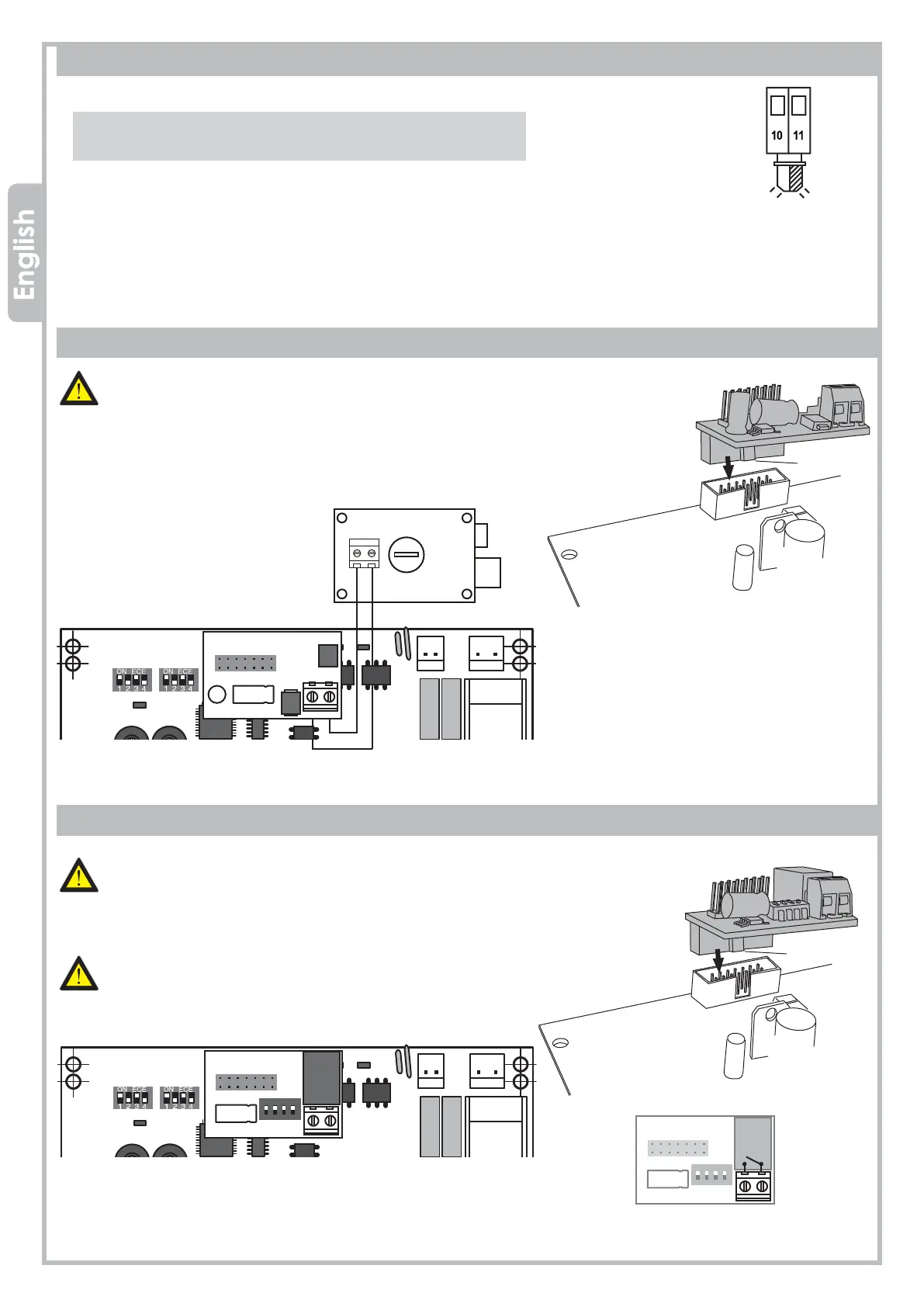
HOW TO PLUG THE 2nd RADIO CHANNEL INTERFACE
slidewey
ATTENTION:
CUT THE POWER OFF BEFORE PLUGGING THE JACK
Plug the MRX01 jack (optional) onto connector J5, respecting
the slot orientation.
Before setting the dip-switch SW1, make sure the power is off.
3.8 FLASHING LIGHT
Wire the flashing light (max 20W) to 10 – 11, terminal JP6.
• QUICK blinking → OPEN
• SLOW blinking → CLOSE
• FIXED light on → PAUSE
3.9 ELECTROLOCK
ATTENTION:
CUT THE POWER OFF BEFORE PLUGGING THE JACK
Plug the MEL04 interface (optional) onto connector J5, respecting the
slot orientation.
Wire the ELECTROLOCK to MEL04.
MEL04
Interface
slideway
MRX01
Interface
contact N.O.
max
1A - 24V
PROTECO S.r.l.
Via Neive, 77 - 12050 Castagnito (CN) ITALY Tel. +39 0173 210111 - Fax +39 0173 210199 info@proteco.net - www.proteco.net
 Loading...