28
Installation
| 28 | Version 1.0
UNPACKING
Hoist should be carefully inspected upon delivery for damage which may have occurred during shipment or
handling. Check hoist frame for: dents or cracks, external cords for damaged or cut insulation, control station
for cut or damaged enclosure, and load chain for nicks and gouges.
1 Chain Bag (Box 1Pcs
2 Control Wire Rope 1m
3 Buon Switch 1 Pcs
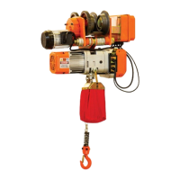
Trolley Installation (models with trolley)
Adjust Trolley Width (models with trolley)
1. Insert suspension pins into lateral plate G and lock it with suspension pin bolts and nuts.
2. Install suspension pin with adjusting disk.
3. Install suspension pin into hanger T. The nameplates of hoist and trolley should be in the same direction.
4. Install additional gaskets into suspension pin before inserting it into lateral plate S.
5. Install outside adjusting disk and spacer pin into suspension pin. Insert cotter pin into spacer pin.
6. Cotter pin should be seen at the left side from front of trolley switch box.
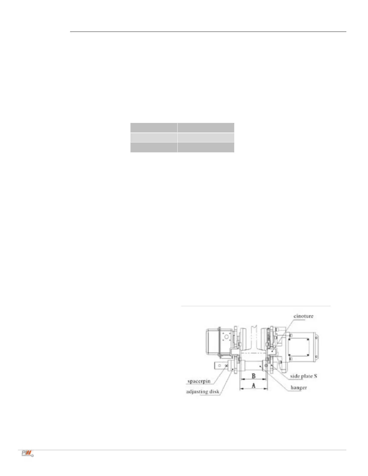
• Adjust width of trolley according to drawing
(below) for appropriate clearance.
• Size A is the dimension of two side plates
that stretch outside completely.
• Size A must be approximate B (the width of
rail ange) + 4mm.
• Adjust size A by increasing or decreasing
adjusting disk. Insert cotter pin into spacer pin
and bend two branches of cotter pin until size
A is correct.
Nut must be tight, insert cotter pin and
bend it completely.
 Loading...