Hardware Overview and Installation
ORiNOCO
®
802.11n & 802.11ac Access Points - Hardware Installation Guide 23
2.4 ORiNOCO
®
AP-9100
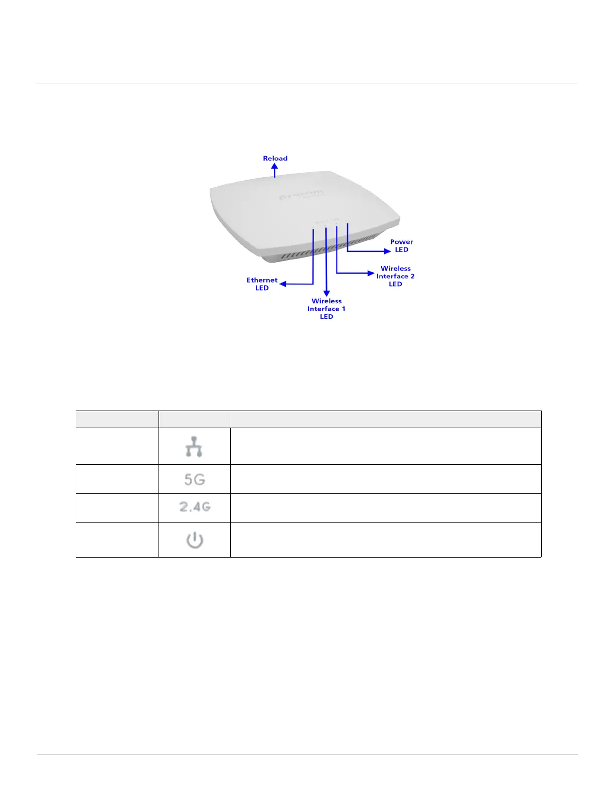
2.4.1 Front View of the Device
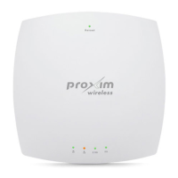
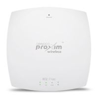
Figure 2-10 Front View of the AP-9100
The front panel of the device contains the following components:
2.4.1.1 LED Indicators
Tabulated below are the four LEDs, that are available on the front panel of the device:
2.4.1.2 Reload
Reload button helps to restore the device to factory default configuration, when:
– The device cannot be accessed through web interface or command line interface.
– The device does not initialize.
– The password is lost.
To avoid tampering, you can lock the reload button on the device and disable the reload functionality. For more details, refer
to the Reload feature and Recovery Procedures illustrated in ORiNOCO
®
802.11n & 802.11ac Access Points - Software
Management Guide.
LED Symbol Description
Ethernet LED This LED indicates the status of the traffic over the wired ethernet
LAN.
5G (Wireless
Interface 1) LED
This LED indicates the status of the traffic over the wireless interface
(radio) 1. Refer Device Operational Modes.
2.4G (Wireless
Interface 2) LED
This LED indicates the status of the traffic over the wireless interface
(radio) 2. Refer Device Operational Modes.
Power LED This LED indicates whether the device is switched ON/OFF.
 Loading...