- 18 -
For use in dry environments only
Please do not dispose off the machine!
N
oise/vibration information
T
he information on vibration and noise emission has been deter-
m
ined in compliance with the prescribed standardised and nor-
mative measuring methods and can be used to compare electri-
cal devices and tools with each other.
T
hese values also allow a preliminary evaluation of the loads
c
aused by vibration and noise emissions.
Warning!
Depending on the operating conditions while operating the
d
evice, the actually occurring emissions could differ from the val-
ues specified above!
Please bear in mind that the vibration and noise emission can
deviate from the values given in these instructions, depending on
the conditions of use of the tool. Poorly maintained tools, inappro-
priate working methods, different work pieces, too high a feed or
unsuitable work pieces or materials or unsuitable bits and cutters
(here: saw blade) can significantly increase the vibration load and
noise emission across the entire work period.
To more accurately estimate the actual vibration and noise load,
also take the times into consideration where the device is
switched off, or is running but is not actually in use. This can
clearly reduce the vibration and noise load across the entire work
period.
Warning:
• Ensure regular and proper maintenance of your tool
• Stop operation of the tool immediately if excessive vibration
occurs!
• Unsuitable bits and cutters can cause excessive vibration and
noises. Only use suitable bits and cutters!
• Take breaks if necessary when working with the device!
Installation and setting up
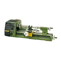
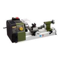
Please lift the machine out of the packaging as shown in Fig. 1a.
Note:
The machine must mot be lifted by the gearbox 23 (Fig. 1) or by
the cover cap of the motor when transporting. The plastic caps
could break.
The supporting surface must be flat and sufficiently strong to
absorb the vibration generated during work. The machine must
be fastened to the surface using the holes 12 (Fig. 1) provided for
this purpose. Ensure that the power cable is
outside the danger zone.
Mount the lathe chuck 2 (Fig. 1) on the main spindle with the 3
screws. Ensure that the chuck seating is free of dust.
All polished metal parts are supplied with a corrosion protection
coating. This is not intended as a lubricant, but as a preservative
only. It must be rinsed off, e.g. with petroleum, before the
machine is used. All guides must be checked and
adjusted if necessary. (See also Chapter „Maintenance”.)
T
he polished guides and spindles must then be well lubricated
with a suitable machine oil. The chuck guard can then be mount-
e
d.
Note:
D
o not oil the any part of the mechanical drive mechanism (belt
pulleys, belts, gearwheels). If there is any excessive noise,
however, it could be advisable to apply a light coat of Molykote
grease to the gearwheels.
Operating:
A
ttention!
B
efore turning on the machine, check that the screws of chuck 2
(Fig. 1) are tightened properly, that the chuck key has been
removed, and that support 16 (Fig. 1) is at a safe distance from
the chuck.
Attention!
Practice without a workpiece clamped in the chuck first. Be sure
to ensure that the turning jaws are tightened securely since they
c
ould be loosened by centrifugal force if there is no resistance.
P
ractice first by running the machine at low speeds.
Please note that the turning chuck has been oiled slightly and
could throw off oil when run for the first time.
Clamping the work piece in the lathe
chuck
Important
If work pieces are clamped in the lathe chuck using the tailstock
without a steady, the projection (Fig. 1b) must not be greater
than three times the diameter of the material
(L = 3 x D).
Note:
The normal lathe chuck has three steel jaws, which are uniformly
adjusted and centre round work pieces automatically.
In the normal position, work pieces can be clamped up to a diam-
eter of 33 mm. After turning the jaws, it is possible to clamp up to
a diameter of 100 mm.
1. Turn the lathe chuck 2 (Fig. 1b) using the wrench 1 until the
work piece fits in the mount.
Important
Do not leave the wrench in the lathe chuck. Risk of injury.
2. Clamp the work piece tightly and remove the wrench from the
chuck.
3. Check the running of the work piece and correct if necessary.
Important
Clamping a longer work piece which has been guided through
the spindle and is projecting to the left increases the risk of
injury. In this case, be particularly careful to ensure that no
objects are caught in the rotating shaft. Protect this zone sepa-
rately by fuse.
Exchanging the clamping jaws (Fig. 1c)
Important
Remove mains plug.
 Loading...