Do you have a question about the Prusa Research Original Prusa MINI and is the answer not in the manual?
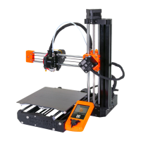
| Build Volume | 180 x 180 x 180 mm |
|---|---|
| Layer Height | 0.05 - 0.35 mm |
| Nozzle Diameter | 0.4 mm |
| Filament Diameter | 1.75 mm |
| Print Speed | up to 200 mm/s |
| Bed Temperature | up to 100 °C |
| Nozzle Temperature | Up to 280 °C |
| Power Consumption | 120 W |
| Supported Materials | PLA, PETG, ASA |
| Connectivity | USB, Ethernet, Wi-Fi |
| Power Input | 100-240 V, 50-60 Hz |
Crucial advice on protecting electronic components from electrostatic discharge (ESD).
Details the parts needed for preparing the Y-carriage.
Lists parts and steps for lubricating the Y-carriage bearings.
Step-by-step guide on how to lubricate the bearings properly.
Continues the process of lubricating bearings, ensuring even grease distribution.
Explains the correct and incorrect orientation of bearings for the Y-carriage.
Instructions for installing the lubricated bearings onto the Y-carriage.
Instructions for mounting the prepared MINI-Y-belt-idler.
Step-by-step guide for assembling the Y-carriage with smooth rods.
Instructions on how to mount the assembled Y-carriage onto the printer frame.
Guides on assembling the Y-axis motor with its pulley.
Instructions for mounting the Y-axis motor onto the rear plate.
Steps for mounting the MINI-Y-rear-plate onto the smooth rods.
Step-by-step instructions for guiding the Y-axis belt.
Guides on properly aligning the Y-axis belt.
Instructions for tensioning the Y-axis belt correctly.
Guides on assembling the MINI-Z-bottom with nuts.
Continues the assembly of the MINI-Z-bottom, including gluing a pad.
Instructions for mounting the Buddy board onto the MINI-Z-bottom.
Guides on connecting the LCD cable to the Buddy board.
Instructions for routing and managing the LCD cable to prevent damage.
Steps for assembling the Z-axis with the Z plate bottom.
Continues the Z-axis assembly, focusing on seating screw heads correctly.
Final steps for assembling the Z-axis, securing parts and inserting screws.
Instructions for connecting the Y and Z-axis assemblies.
Steps for joining the Y and Z-axis assemblies, tightening screws partially.
Further steps for joining the Y and Z-axis assemblies, securing with screws.
Guides on how to correctly align the assembled YZ-axis components.
Instructions for finally securing the aligned YZ-axis assembly.
Steps for routing the Y-axis motor cable through the chassis.
Final guidance for the Y-axis motor cable routing.
Instructions for inserting nuts into the MINI-Z-top part.
Steps for assembling the Z-axis motor and MINI-Z-top.
Guides on how to mount the Z-axis smooth rods into the MINI-Z-bottom.
Instructions for installing bearings onto the Z-axis rods.
Guides on assembling the X-axis, sliding on bearings and pushing the X-end.
Guides on mounting the X-carriage onto the bearings.
Guides on mounting the X-axis assembly onto the Z-axis.
Continues mounting the X-axis, securing the trapezoidal nut.
Instructions for mounting the Extruder motor and front part.
Continues assembling the Extruder, fitting gears and checking movement.
Steps for assembling the Extruder, securing the rear part and cables.
Guides on mounting the MINI-Extruder-idler, securing it with a screw and spring.
Instructions for mounting the assembled extruder onto the Z-carriage.
Continues mounting the extruder, attaching the inspection door.
Instructions for mounting the hotend assembly onto the X-carriage.
Guides on mounting the print fan onto the X-carriage.
Instructions for installing the SuperPINDA sensor onto the MINI-minda-holder.
Instructions for assembling the heatbed, connecting wires and tightening screws.
Instructions for mounting the heatbed assembly onto the Y-carriage.
Instructions for mounting the LCD onto the printer's holder.
Guides on connecting the LCD cable to the Buddy board.
Guides on connecting the power switch cables to the Buddy board.
Guides on connecting various cables to the Buddy board in order.
Continues connecting electronics cables, referencing a wiring diagram.
Crucial steps for adjusting the SuperPINDA sensor height.
Instructions for connecting the power supply and preparing the heatbed sheet.