8 (701) 566-0452
h1
h1
h2
h3
h3
h4
4A
18
17
TOP
BOTTOM
4B
4D
4C
8
10
h2
h5
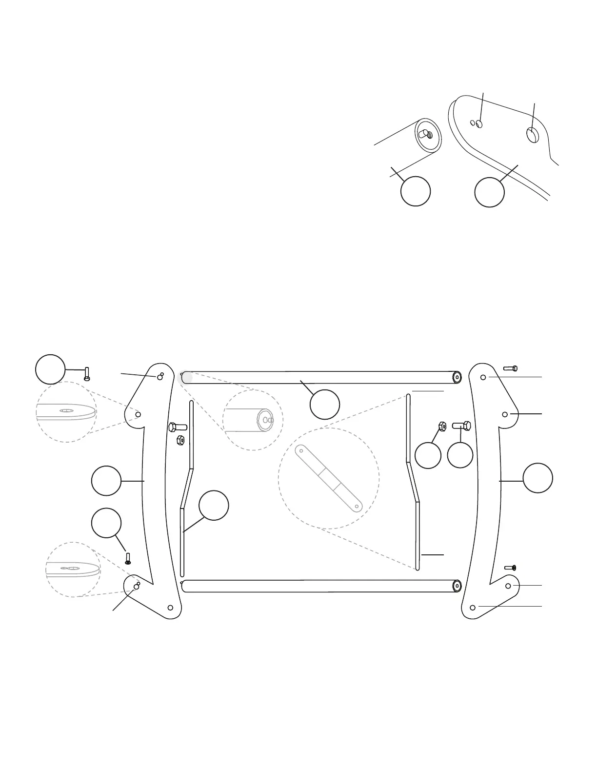
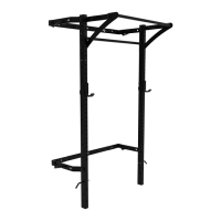
Assemble Extended Pull-Up Bar
1. Lay out parts 4A through 4D to match the diagram below.
Pay close attention to the holes h1 & h3 on 4A. Only one of
the support sides (4A) will have a divot for the pull-up
bar stud on 4B
2. The Right and Left Arms (4D) should be angled outward on
the bottom section of the extended pull-up bar.
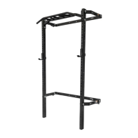
3. Using M8 x 30 Hex Head Bolt (17) attach Left Support (4A)
to a Bar (4B) through h1. The stud on the Bar (4B) should
t into the divot of Left Support (4A) during assembly.
Then repeat on the other side with the Bar (4B) and Right
Support (4C). Fully tighten the pull-up bar as this will reduce
movement of the bar while in use
4. Using M8 x 25 Allen Bolt (18), attach Left Support (4A) to the Bar (4B) through h3 and repeat with the
Bar (4B) and Right Support (4C)
5. Attach Left Arm (4D) to Left Support (4A) through h2 of both pieces using M16 x 35 Hex Head Bolt (8)
and M16 Nylock Nut (10). Repeat with Right Support (4C) and Right Arm (4D)
h1
h2
4B
4A