EasyManua.ls Logo

PRx Performance Profile PRO User Manual

Default Icon
11 pages
To Next Page IconTo Next Page
Page #1 background imageLoading...
Page #1 background image
060223_Rev. 1
Tool List
15/16” Open End Wrench
7/16” Open End Wrench
1/2” Open End Wrench
15/16” Socket
1/2” Socket
Ratchet
4’ Level
Plumb Bob
7/32” Drill Bit
Cordless Drill
Impact Driver
Stud Finder
Tape Measure
Pencil
Item #
Description
Qty.
1
Left Wall Bracket
2
2
Right Wall Bracket
2
3
5/16” x 2-1/2” Lag Screw
8
4
5/16” Flat Washer
8
5
5/8” Flat Washer
16
6
5/8” Lock Nut
12
7
5/8” x 4-1/2” Hex Bolt
4
8
5/8” x 1-3/4” Hex Bolt
4
9
5/8” x 1-1/2” Hex Bolt
2
10
5/8” x 5” Hex Bolt
2
11
90” Upright
2
12
Bent Hitch Pin (not shown)
1
13
Plastic Spacer
8
14
Linkage Arm
4
15
Gas Shocks
4
16
Flange Nuts
8
17
Kipping Bar
1
18
Kipping Bar Arm
2
19
Kipping Bar Spacer
2
90” Profile® PRO Rack with Kipping Bar
This installation requires two people.
Standard installation is designed for ceilings 108” or taller. If your ceilings are
shorter than 108” please refer to the table on page 3 and use the bracket height
measurements that correspond to your ceiling height.
Question and Answer IconNeed help?

Do you have a question about the PRx Performance Profile PRO and is the answer not in the manual?

PRx Performance Profile PRO Specifications

General IconGeneral
BrandPRx Performance
ModelProfile PRO
CategoryFitness Equipment
LanguageEnglish

Summary

Getting Started

Check Stud Spacing

Verify wall stud spacing is standard 12”, 16”, or 24” for mounting.

Check Wall Width and Clearance

Ensure wall width allows 48” stud spacing and 32” clearance on each side.

Check Ceiling Height and Modifications

Confirm ceiling height (108”+) and refer to page 3 for shorter ceilings.

Modified Ceiling Height Installation

Installing Wall Brackets

Determine Floor Slope & Starting Stud

Identify floor slope and select the starting far-left or far-right stud.

Mark & Drill Bracket Holes

Mark 21”, 90” from floor & 4” below; drill 2-1/2” deep with 7/32” bit.

Mount First Wall Bracket

Align upper bracket, use level, fasten with 5/16” lag screws and washers.

Space & Mount Second Wall Bracket

Span 48”, level second bracket, mark, drill, and fasten with lag screws.

Set Bracket Spacing & Final Tighten

Measure 45-1/2” between brackets, level, and tighten all lag screws.

Assemble and Attach Linkage Arms

Attach Gas Shocks to Linkage Arms

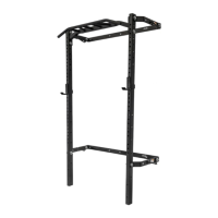
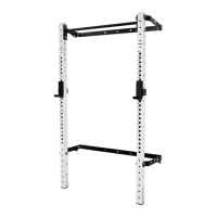
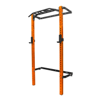
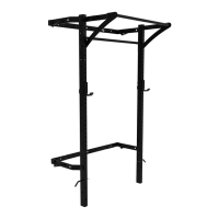
Connect gas shock barrel to linkage arm outer face with flange nut.

Mount Linkage Arms to Wall Brackets

Attach linkage arms to wall bracket ears using hex bolts, washers, and lock nuts.

Connect Linkage Arms to Uprights

Bolt linkage arms to uprights using hex bolts, washers, plastic spacers, and locknuts.

Attach Kipping Bar Assembly

Connect Kipping Bar to Uprights

Attach Kipping Bar to uprights using hex bolts, washers, and lock nuts.

Secure Kipping Bar Arms

Align and attach kipping bar arms to uprights using hex bolts and lock nuts.

Attach Gas Shocks to Rack

Secure Rack in Up Position

Use bent hitch pin to lock the rack in the folded up position.

Fasten Gas Shock Flange Nuts

Insert gas shock stud into wall bracket, tighten flange nut with 1/2” wrench.

Related product manuals