PS Engineering
PMA8000BT Audio Selector Panel and Intercom System
Installation and Operator’s Manual
200-890-0702 Page 2-5 Rev. 1, Oct. 2010
Unswitched #1 is presented to the pilot headphone in fail-safe (off) mode.
NOTE
Inputs 1, 2 and 4 are fixed (1:1), and any audio level adjustments must be made at the input source.
Unswitched #3 has a variable adjustment control located on the bottom side of the unit. This control al-
lows you to adjust the volume level of that unswitched input. Refer to Adjustments section.
The front panel jack can be configured to act as a fifth unswitched input. When configured through the
front panel function switches (see operational section), the audio input to this jack will be presented to the
pilot and copilot headsets, and not muted.
NOTE
The front-mounted utility jack is intended for portable equipment that is advisory in nature. It is NOT
INTENDED for use as a primary warning channel. Audio of importance MUST ALWAYS be hard-wired
into the unswitched inputs of the audio panel.
2.4.9 "Swap" Mode
When a momentary, normally open, push-button switch is connected between pin 20 on the J2 connector
and aircraft ground, the user can switch between Com 1 and 2 by depressing this switch without having to
turn the mic selector switch. This yoke-mounted switch eliminates the need to remove your hands from
the yoke to change transceivers. The transfer of TX indication from Com 1 to Com 2 shows that the swap
has been initiated; there is no dedicated swap indicator.
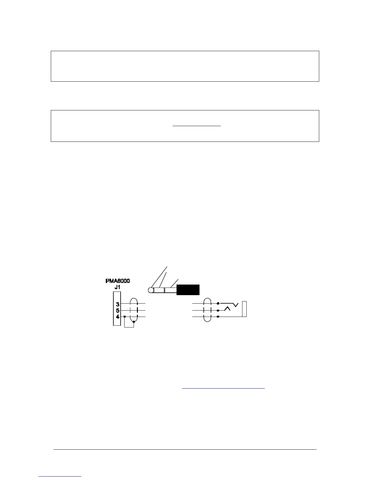
2.4.10 TEL (Duplex) Function for Cell Phones
Audio streams selected by the intercom mode are provided to the Tel output, and audio from Tel is pr e-
sented to the headset. This allows a telephone-like audio interface.
The TEL mode in the PMA8000BT is compatible with many cellular telephones with hands-free headset
interfaces. The front panel 3/32” utility jack can be used as the interface to the Cell Phone, or a jack can
be installed somewhere on the aircraft panel. The wired interface jack is connected with the PMA8000BT
as shown: A patch cord (3/32” to 3/32”) is available from PS Engineering under P/N 425-006-7026.
Figure 2-1 Cellular telephone interface for rear connector, if an additional jack is desired
The PMA8000BT is compatible with most Bluetooth® enabled devices for making and receiving tele-
phone calls through the aircraft audio system. Visit www.ps-engineering.com/support to see a list of tested
phones.
2.4.10.1 Cell phone Sidetone
As shipped from PS Engineering, the PMA8000BT does NOT provide cellular telephone sidetone (the
user’s voice fed back to the headset). Some cell phones do not provide sidetone. In PMA8000BT audio
panels above serial number W04748, Telephone sidetone can be enabled by pressing the TEL and ADF