PS Engineering
PMA8000BT Audio Selector Panel and Intercom System
Installation and Operator’s Manual
200-890-0702 Rev. 1, Oct. 2010
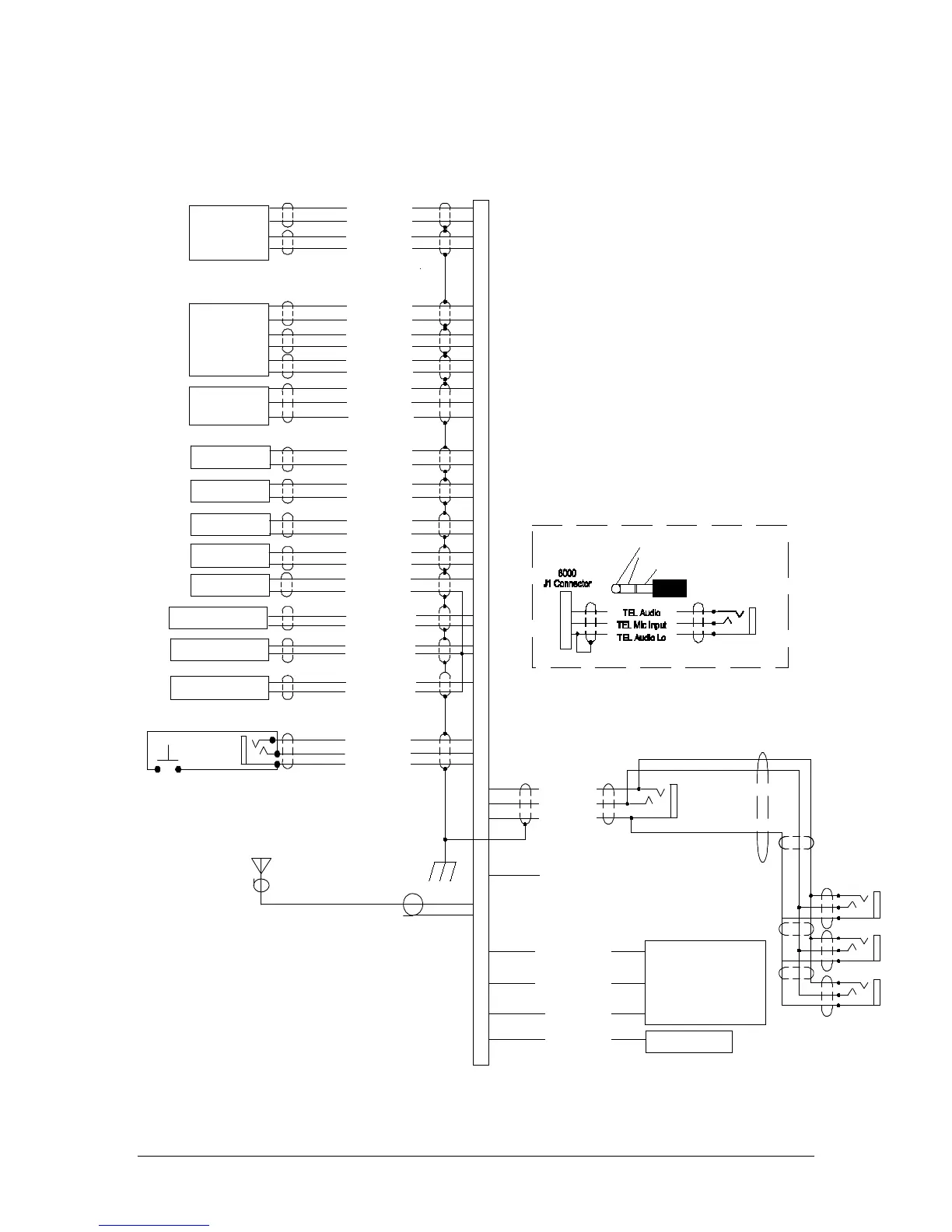
Appendix C – J1 Connector Interconnect
Co m 1 A ud io Hi
Co m 1 M ic K e y
Co m 1 L o
Communications
Transceiver #1
Communications
Transceiver #2
Nav 1 A ud io H i
Nav 1 A ud io L o
VHF Nav 1
Nav 2 A udio Hi
Nav 2 A udio L o
VHF Nav 2
DM E A udio Hi
DM E A udio Lo
DME Receiver
Com 2 SPR Load
Uns w itched I np ut #1 H i
Uns w itched A ud io L o
Unswitched Audio #1
Uns w itched I np ut #2 Hi
Uns w itched A ud io L o
Unswitched Audio #2
P ilot M ic Aud io H i
Pilot Mic PTT
P ilot M ic L o
36
37
38
39
MKR Ant.
1
2
RG -5 8A / U Co a x
9
10
11
12
Co m 1 M ic A ud io H i
Co m 2 A ud io Hi
Co m 2 M ic K e y
Co m 2 L o
13
14
15
30
Co m 2 M ic A ud io H i
17
18
19
20
21
22
Co m 2 S p r L o ad
Co m 2 S p r L o ad
27
28
31
32
44
43
33
34
35
Telephone
3
4
5
TE L A udio Hi
TE L M ic A ud io Hi
TE L A udio L o
A DF A udio Hi
A DF A udio Lo
ADF Receiver
7
8
Notes:
1. All shields should be grounded at audio panel only.
Other end remains floating.
2. All Power, and Ground wires shall be #22 gage wire
Lighting #22 AWG, other wires minimum #24 AWG
3. All mic and headphone jacks must be isolated from ground.
4. Speaker loads may be required on some older transceivers.
Consult manufacturer's information.
COM 2 Speaker load is the only one provided in the PMA8000.
5. All shielded wires must be MIL 22750 or 27500.
6. Unswitched inputs 1, is always presented to speaker
and crew headphones, regardless of SPR switch or PTT.
7. COM active output provides a logic low when there
is activity on COMs or other selected audio. This is used to prioritze
audio warnings in some systems.
8. No connection to pins 25, and 26
9. DME audio is passed when AUX button is pressed
10. Unswitched #3 is adjustable
11. Unswitched #2 is selectable over the speaker
Pilot PTT
See Note 4
PMA8000B Connector, J1 (Sub-D 44-pin, male on tray)
Uns w itched I np ut #3 H i
Uns w itched A ud io L o
Unswitched Audio #3
29
See Note 6, 10 & 11
P as s. P ho nes (R )
P as s P hone s ( L)
P as s. P ho nes L o
P as s. 1 Pho ne s Jack
P as s. 4 P ho nes Jack
Ext. Marker Lamp (Blue)
Ext. Marker Lamp (White)
Ext. Marker Lamp (Amber)
MM Sense Output
White Lamp Output
Blue Lamp Output
Amber Lamp
MM Sense
Ext. Marker Annunciator
P as s. 3 P ho nes Jack
P as s. 2 P ho nes Jack
24
COM Active Output
3/32" Cellular Jack
3
5
4
Ce llula r Pl ug (t y pi ca l)
Tip= Microphone out
Ring= S pe a k er a ud io
B as e = G round
Cellular Phone
Interconnect
See Note 7
A UX A udi o Hi
A UX A udi o Lo
AUX Receiver
23
41
40
42