Computer Graphics (VGA)/Stereo Audio Matrix Switcher
6. External Connection
6.1 Introduction of the Input and Output Connectors
The MVG matrix switchers adopt female 15-pin HD connectors as the video signal I/O interface, and
captive screw connectors as the audio signal I/O interface. Please refer to the rear view figure of the
model concerned for details.
6.2 Connection of RS-232 Communication Port
Except the front control panel, infrared remote controller (Optional) and the Ethernet control (Optional),
the MVG matrix switcher can be controlled from far-end control systems via the RS-232 communication
port.
This RS-232 communication port is a female 9-pin D connector. The definition of its pins is as the table
below.
Pin RS-232 Description
1 N/u Not used
2 Tx Transmit data
3 Rx Receive data
4 N/u Not used
5 Gnd Signal ground
6 N/u Not used
7 N/u Not used
8 N/u Not used
9 N/u Not used
6.2.1 Connection with Control Systems
With the RS-232 port, can control and communicate with the switcher remotely.
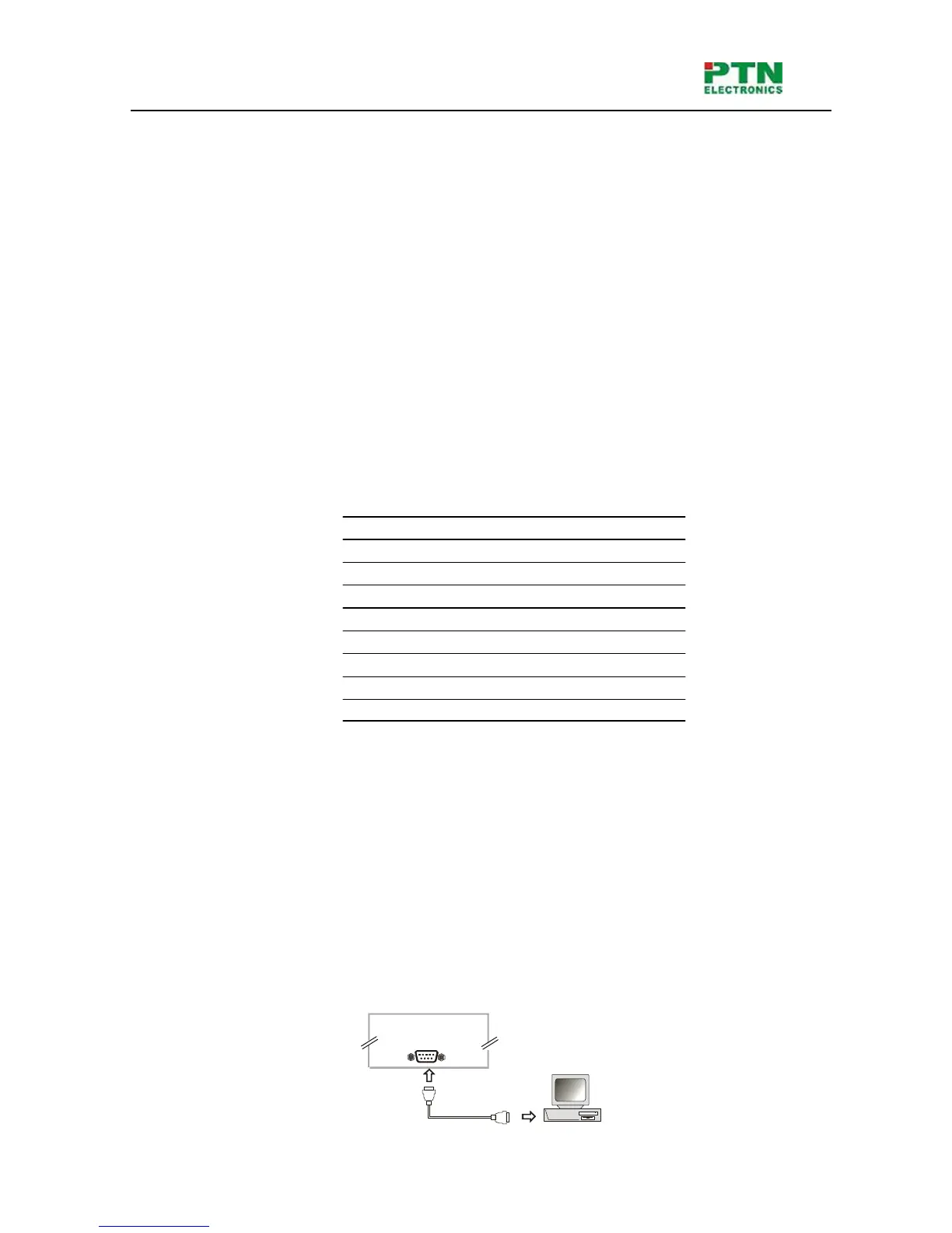
6.2.2 Connection with Computer
When the switcher connects to the COM1 or COM2 of the computer with control software, users can
control it by that computer.
To control the switcher, users may use the RS232 software.
RS-232
Computer for controlling
Conver t er