Main Run Page
The main run page gives the user a snap shot of the current status of the dust collector.
There is a lot of information on this screen so please take a minute to read this section.
1
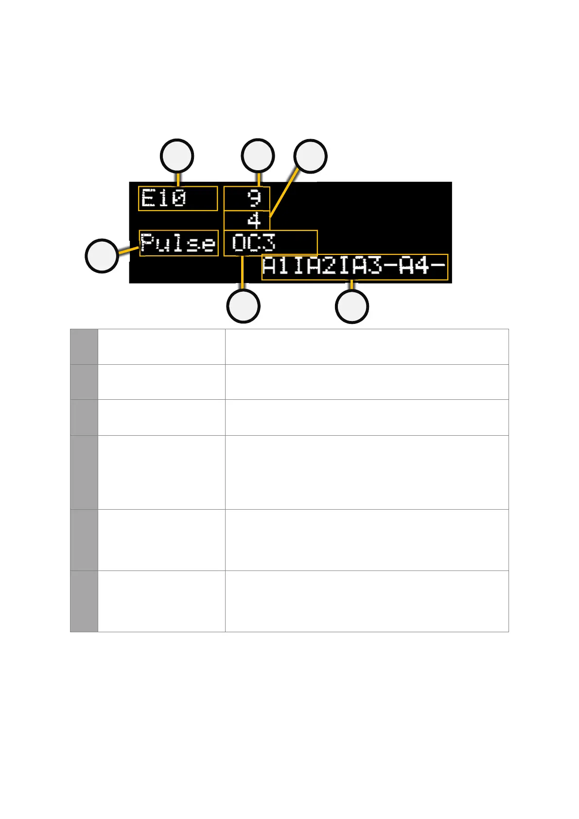
MODEL OF PTronik
CONTROLLER
Indicates the model of the PTronik controller. Visually the E10, E10
and E10 look very similar.
2
COUNT DOWN TIME Indicates the time in seconds until the next valve pulses.
3
NEXT VALVE Indicates the next valve that will pulse. This will be a number
between 1 and 240 depending on setup and how many extension
cards are connected.
4
ALARM STATE Indicates the alarm status for alarms 1 to 8 (the screen will toggle
between A1IA2IA3-A4+ and A5IA6-A7-A8-).
• I = Interrupt
• - = alarm disabled
• + = alarm enabled
• * = alarm enabled and ON (activated)
5
SOLENOID STATE Indicates the last solenoid valve that fired and what the result of the
valve as (whether the coil of the last valve is faulty or not).
• OK = NO Fault
• OC = Open Circuit
• SC = Short Circuit
6
MANUALLY STOPPING THE
DUST COLLECTOR
Indicates the current state of the controller. The dust collector can
be manually halted if required.
• Halt = The dust collector has been halted either manually or
by the differential pressure cleaning mode
• Pulse = The dust collector is pulsing
If any of the three buttons are pressed the following screen will appear. This allows the user
to change between pulsing or halting and allow the user to enter the Menu section.