9
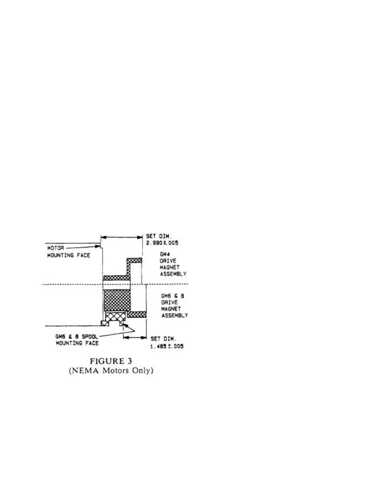
7. Install the drive magnet assembly (Item 21)
onto the motor shaft to the dimension shown in
Figure 4. If the motor is metric install the motor
adaptor (Item 29) using motor bolts (Item 25) to
the motor at this time. Also install the drive
magnet assembly onto the motor shaft until it
butts up against the shoulder on the motor
shaft. Tighten the drive magnet setscrews (Item
24) to 35 inch lbs. (395 Ncm). These setscrews
have a special nylon patch applied to the
threads to prevent loosening.
8. Carefully assemble the motor/drive magnet
assembly to the pump casing. Be careful not
to chip the drive magnets when slipping them
over the can or to pinch your fingers when the
two assemblies snap together. The use of (4)
assembly guide pins (Part #79637) is
suggested. Use guide pin (Part #49639) for
metric motors. See Figure 2. Install motor bolts
(Item 25) or adaptor bolts (Item 30) for metric
motors.
.
9. Reinstall pump in system, open inlet and
discharge valves and start pump. Monitor pump
for 5-10 minutes for signs of binding, excessive
noise and motor amperage draw. Check
performance. If problems are encountered refer
to the Troubleshooting Section.
GMC6 & GMC8 SERIES REFERENCE
DRAWINGS: SD2580
DISASSEMBLY
1. Close discharge and suction valves.
2. Disconnect power source to motor.
3. Flush and drain pump then remove pump from
the piping. Do not forget to drain the can area
through the front housing drain plug (Item 27).
4. Remove the four casing bolts (Item 35) which
are orientated vertically and horizontally.
Do not remove the motor bolts (Item 23) or the
recessed front housing bolts (Item 26) which
have protective plugs and are orientated at 45°
to vertical and horizontal, at this time.
5. Separate the spool and casing (Item 20) by
pulling them apart. This will take physical force
because you are pulling against the magnetic
attraction of the drive to the driven magnet. Do
not pry but pull straight apart.
6. Do not remove the drive magnet assembly
(Item 21) from the motor unless it or the motor
are to be replaced. This will make reassembly
easier later. The drive magnet assembly is
removed by loosening the setscrews (Item 24)
and sliding it off the motor shaft. Access to the
setscrews is provided through hole in the
spool. Remove the spool from the motor at this
time if desired.
7. Remove the recessed front housing bolts. You must
first remove the protective plug. This will allow the
casing and can (Item 19) to be separated from the
front housing (Item 3). Note: Any remaining fluid
left in the can will now drain out.
8. Remove the retaining ring (Item 14) on the
 Loading...