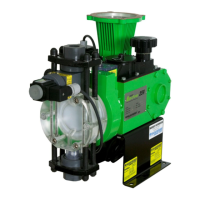
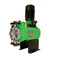
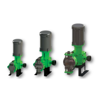
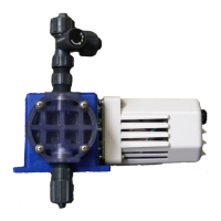
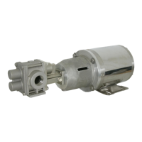
The document describes the PULSAR® HYPOPUMP2® Auto De-Gas Metering Pump, referred to as the "ADV" in the manual. This addendum provides additional information for Pulsafeeder PULSAR® and PULSAR Shadow® metering pumps equipped with the Auto De-gas Valve, which is designed for purging trapped gases from the reagent head. It is crucial to reference the latest revision of the complete PULSAR® or PULSAR Shadow® pump IOM for critical safety and operational information alongside this addendum.
Function Description:
The ADV is a gas handling/priming aid designed to operate solely with Pulsafeeder PULSAR® and PULSAR Shadow® metering pumps. Its primary function is to prevent "air binding" and loss of prime in reciprocating metering pumps, which often handle chemicals like sodium hypochlorite that produce gas within piping and pump systems. Gas accumulation in the pump reagent head can impede pump operation. The ADV addresses this by periodically opening a pressure-balanced valve, allowing a small amount of pressurized fluid from the discharge line to bleed back into the pump head. This action helps maintain prime and displaces gas through the discharge check valve. The valve is actuated by a solenoid controlled by a solid-state timer, which is factory preset to open for 0.25 seconds every 30 seconds. This timing is optimized for gas handling with minimal pump capacity loss. The ADV Valve Assembly features a dual sealing design to ensure continued function even if the primary bellows seal fails. A Leak Detection Port (1/8” NPTF) provides a visual indication of a bellows failure and can be used to pipe any leakage to a safe vessel or a leak detection device. The automatic valve assembly can operate independently of the pump motor and/or controls.
Usage Features:
The ADV is designed for ease of use and maintenance. It includes a Manual Override Button, which serves as a fast priming aid. For optimal results, the button should be depressed for 1 second every few seconds, rather than held down continuously. The ADV is available in two voltages: 115 VAC, 50/60 Hz, 0.2 A, or 230 VAC, 50/60 Hz, 0.1 A, with the specific voltage indicated on the enclosure label. The electrical components are housed in a NEMA 4X (IP 65) enclosure, which is isolated from the pumped fluid. For installation, the ADV should be mounted in an area with at least 6 inches of clearance from the front of the enclosure to facilitate removal and re-installation. It is important to avoid locations subject to extreme cold, heat, or direct sunlight, as these conditions can damage the ADV and void its warranty. Minimum operating temperature is 0° Celsius / 32° Fahrenheit, maximum for PVC construction is 49° Celsius / 120° Fahrenheit, and maximum for PVDF construction is 65° Celsius / 150° Fahrenheit. Electrical installation must conform to all relevant codes and be performed by a qualified electrician, with all power disconnected before servicing. It is recommended to power the ADV from a Ground Fault Circuit Interrupter (GFCI) protected electrical circuit. Flexible conduit or cable, at least 18 inches long, should be used for wiring to allow for easy removal of the valve assembly for cleaning or maintenance.
Maintenance Features:
Maintenance of the ADV involves several key procedures to ensure its longevity and proper function. The O-ring seals in the check valve and ADV are critical for product containment and pump operation. These O-rings should be inspected carefully for damage or wear and replaced as needed, especially whenever the ADV assembly is removed from the pump. A complete cartridge seal assembly and the entire ADV assembly are available as repair parts.
The Auto De-gas Valve Seal Kit Replacement (NP999130-000) procedure involves:
- Disconnecting power to the pump drive motor and ADV.
- Relieving all pressure from the piping system and following safety protocols for fluid exposure.
- Removing the cap nut from the front of the solenoid and sliding off the solenoid.
- Loosening and removing the union nut, which may release pumped fluid.
- Removing the core tube assembly.
- Removing the outer spring from the core assembly and pulling out the core assembly.
- Inspecting and removing any O-rings left in the valve body.
- Removing the sleeve from the core tube and then removing the O-ring.
- Locating parts from the seal kit, ensuring the small spring is in the core. A caution is given not to unscrew any part of the seal kit during inspection or reassembly, as this can affect valve performance.
- Installing a new O-ring onto the core tube, lubricating it with a product-compatible lubricant, and reinstalling the sleeve over the core tube.
- Installing a new O-ring on the seal kit, again using a compatible lubricant.
- Applying a compatible lubricant to the body O-ring and installing it into the valve body.
- Carefully installing the new seal kit straight into the valve body bore.
- Installing a new spring over the core and verifying the small spring is still in the core.
- Sliding the core tube over the core and aligning it with the tabs on the valve body.
- Sliding the union nut over the core tube and hand-tightening it onto the body.
- Sliding the solenoid over the core tube and securing it with the cap nut, hand-tight.
- Reapplying power to the pump and ADV and following standard startup instructions.
The Valve Body and Discharge Valve Assembly Removal procedure is also detailed:
- Disconnecting power to the pump drive motor and, if maintaining the ADV itself, from the ADV unit.
- Relieving all pressure from the piping system.
- Closing inlet and outlet shutoff valves.
- Taking precautions against environmental and personnel exposure to hazardous materials.
- Loosening suction valve tiebar bolts and shifting suction piping to drain liquid from the reagent head cavity.
- Loosening discharge valve tiebar bolts and shifting piping to drain liquid.
- Sliding the valve assembly away from the front of the reagent head, being careful not to let check valve parts fall out.
- Removing and cleaning or replacing discharge check valve components once the ADV is separated.
- Reinstalling in reverse order, ensuring the oval-shaped O-ring at the bottom of the valve assembly is correctly positioned.
Troubleshooting guidance is provided for common issues such as the pump not priming, low pump delivery, leakage from the leak detection port, and the valve failing to actuate, with probable causes and possible solutions. The manual also includes instructions for Hypo Valve Replacement, which involves removing the old valve, disconnecting power, removing tie bar nuts and the valve cap, and then installing the new valve body assembly, solenoid, and electrical enclosure, followed by wiring and reassembly.