
C
courtney71Aug 18, 2025
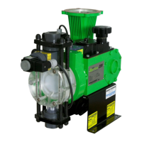
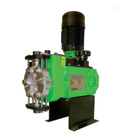
Why Pulsafeeder PULSAR 25HJ does not start?
- WWanda DillonAug 18, 2025
If your Pulsafeeder Water Pump doesn't start, it could be due to several reasons. The coupling might be disconnected, so ensure it is properly connected. There might be an issue with the power source, so check that. A blown fuse or circuit breaker could also be the cause; replace them, addressing any overload. Look for any broken wires and repair them. Verify that the pump is wired correctly by checking the wiring diagram. Finally, check for any blockages in the pipe or line and open the valves.