7.3 CHECK VALVES
7.3.1 General Description
Most fluid metering problems are related to check valves.
Problems usually stem from solids accumulation between
valve and seat, corrosion of seating surfaces, erosion, or
physical damage due to wear or the presence of foreign
objects.
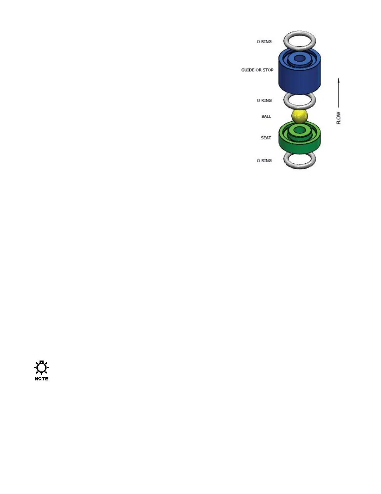
The valve incorporates a ball, guide, and seat. Flow in
the unchecked direction lifts the ball off the seat, allowing
liquid to pass through the guide. Reverse flow forces the
ball down, sealing it against the sharp edge of the seat.
The guide permits the ball to rotate but restricts vertical
and lateral movement in order to minimize “slip” or
reverse flow. Ball rotation prolongs life by distributing
wear over the entire surface of the ball. Since ball return
is by gravity, the valve must be in the vertical position in
order to function properly. Parts are sealed by O-rings.
7.3.2 Removal, Inspection, and Reinstallation
Use the following procedure to remove, inspect and reinstall the check valves:
1. Disconnect the power source to the drive motor.
2. Relieve all pressure from the piping system.
3. Take all precautions to prevent environmental and personnel exposure to hazardous
materials.
4. Close the inlet and outlet shutoff valves.
5. Loosen the suction valve tiebar bolts and spring the suction piping slightly to drain any liquid
from the reagent head cavity. If the piping is closely connected it may be necessary to
disconnect a union or flange.
6. Remove the suction check valve assembly (ball contained within guide and seat), holding it
together as a unit.
7. Loosen the tiebar bolts on the discharge valve and spring the piping slightly to drain any
liquid.
8. Remove the discharge check valve assembly, holding it together as a unit as before.
9. Disassemble both valves and examine components for wear. Seats should have sharp
edges or a small chamfer, free from dents or nicks. Hold the ball firmly against its mating
seat in front of a bright light to inspect for fit.
Observation of light between ball and seat is cause for replacement of either or both
components. For best results, always loosen the unions or flanges on either side of the
system piping prior to re-tightening of the check valve assemblies. Retighten the unions
or flanges after the check valves are securely tightened into position.
10. Reassemble both valves using new parts as required. Sealing O-rings should always be
replaced.
11. Reinstall both valve assemblies, taking care to ensure that they are correctly oriented with
balls above seats.
12. Tighten the tiebar bolts evenly, making sure the valve assemblies are assembled squarely.
Refer to Appendix IV for torque values.
13. Check for leaks and retighten tiebar bolts as necessary.
 Loading...