ENGLISH
•
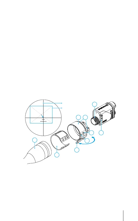
If the Ring Adaptor (12) with the insert (11) selected according to the table
cannot be mounted onto the lens (10), follow the steps below:
- Loosen the locking screw (14) with a 2mm Allen key.
- Untighten the screw (15) with a hex wrench (S = 4mm) until the Ring
Adaptor with the insert can be mounted onto the lens (10).
•
Move the lever (16) from its initial OPEN position to the CLOSE position.
•
Loosen the locking screw (14) with a 2mm Allen key, if it hasn’t been done
before.
•
Tighten the screw (15) using a 4mm Allen key. The clamping force should be
1.5-2 Nm (use a torque screwdriver) to ensure the lever is correctly tightened
(16), while the Ring Adapter with the attachment should not move relative to
the body of the optical sight (10). If necessary, tighten or loosen the screw
(15) to operate the lever (16) in the best way possible.
•
Tighten the locking screw (14) as far as it will go.
•
Turn on the attachment by briey pressing the ON button (6).
•
Align the display center with the crosshairs of the reticle by tilting the
attachment.
•
Align top and bottom display boundaries parallel to the horizontal axis of the
optical sight by turning the attachment clockwise or counterclockwise.
•
Having reached the best possible position of the attachment, tighten the two
screws (13) until stop. The clamping force should be 6.5-7.5 N·m (use a torque
screwdriver to check).
Open
Close
16
12
10
11
13
15 9
14
17
Display of attachment
Crosshair
Powering on and image setup
•
Remove the lens cover (1).
•
Press the ON button (6) to turn on the attachment.
•
If necessary, adjust the reticle sharpness according to the instructions for
your scope.
•
Enter the main menu with a long press of the controller button (8) and select
the desired calibration mode: manual (M), semi-automatic (SA) or automatic (A).
•
Calibrate the image by briey pressing the ON button (6). Close the lens
cover before manual calibration.
6
 Loading...