4TOLB-3L1
1306, Issue 2, May 1992
10
Prescription Alignment
This procedure consists of selecting the desired switch positions. Figure 3 shows the
location of the switches; Table 2 provides option selection instructions.
1) TRMT and RCV Attenuation—Each attenuation switch on the pc board is marked
with an attenuation value in dB, which is added to the circuit when the switch is
placed in the IN position. Set the option switches to the desired positions
corresponding to the transmit/receive attenuation and gain/loss values. The TRMT and
RCV attenuation functions and the appropriate TLP values are shown in Figure 6. The
proper attenuation values are selected as shown below.
a) To determine the proper TRMT attenuation value, first identify the input TLP and
then apply the following formula: TRMT Attenuation = Input TLP + Insertion
Gain + 8.5 dB. For example, with an input TLP of 0 dB, the TRMT attenuation
would be 0 + 7.5 dB + 8.5 dB = 16 dB.
b) To determine the proper RCV attenuation value, first identify the output TLP and
then apply the following formula: RCV Attenuation = +4 dB + Insertion Gain –
Output TLP. For example, with an output TLP of 0 dB, the RCV attenuation
would be 4 dB + 3 dB – 0 = 7 dB.
2) Channel Bank Type, LB Mode, and Sealing Current—Select these options by placing
the switches to the proper positions. See Figure 3, Table 2, and section 3A.
Verified In-Line Alignment
This procedure uses a transmission measuring set (TMS) such as the H.P. 4937A, the
front-panel TEST jack of the unit, and MAC jack to bantam jack adapter, such as the
Pulsecom B105097 or equivalent. An extender card can be used to provide easy access to
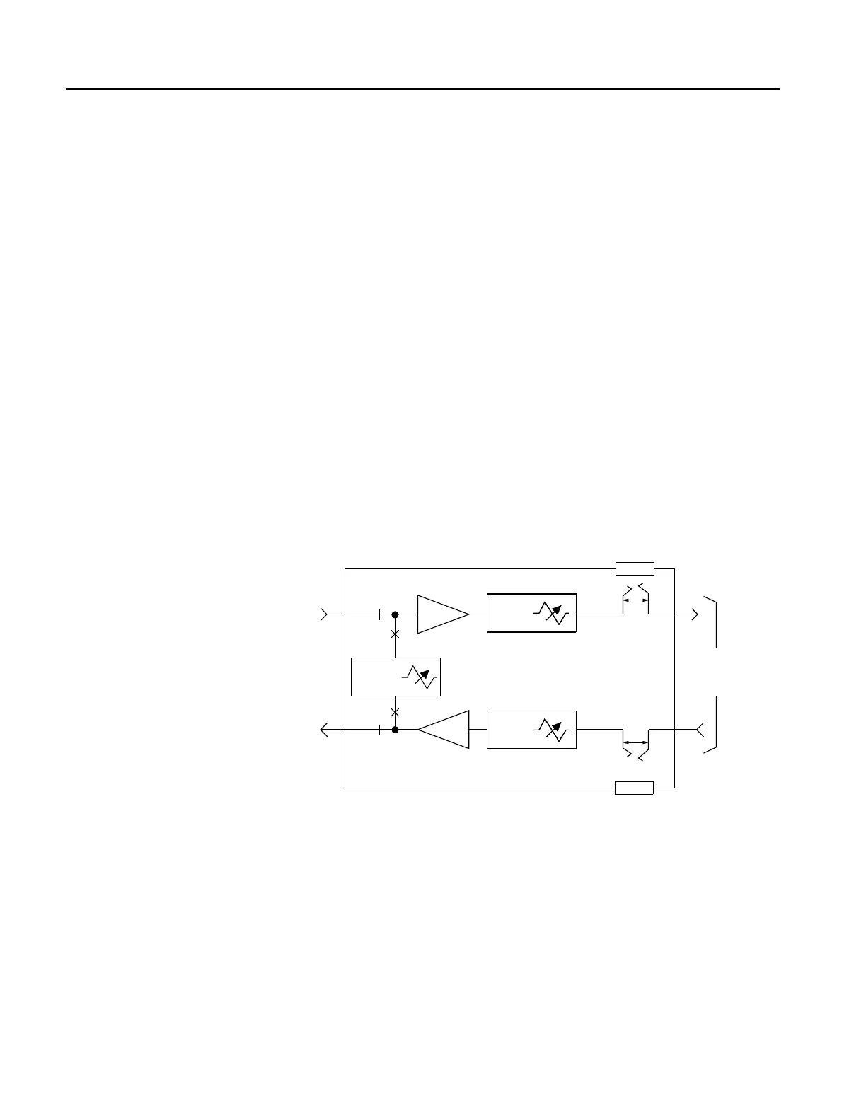
Figure 6. 4TOLB-3L1 Level Settings
1
7
- 8.5 dB
TLP
+4 dB
TLP
TRANSMIT PATH
TRMT ATTN =
INPUT TLP + 16 dB
RCV ATTN =
7dB - OUTPUT TLP
RECEIVE PATH
+7 dB to
-17 dB TLP
P/O J1
P/O J1
TRMT
+7.5 dB
+3 dB
0 to
32.5 dB
S1 & S2
3 9
0 to
24 dB
S3 & S4
TO
CHANNEL
BANK
+16.5 dB to
-16 dB TLP
RCV
T
R
0 to
±31.75 dB
LOOPBACK
PATH
LB
LB