4TOLB-3L1
1306, Issue 2, May 1992
4
3. INSTALLATION AND ALIGNMENT
WARNING
This unit includes components that are susceptible to damage from static
electricity. DO NOT handle units without protection from electrostatic
discharge (ESD).
CAUTION
1. When replacing older 4TOLB units, reconnect loopback function leads
on the backplane. See Table 1.
2. Use a 325A power converter unit if a 48-channel bank is to be filled
with 4TOLB-3L1 plugs. The standard power module may not be able to
supply sufficient +12V power.
A. Options
General
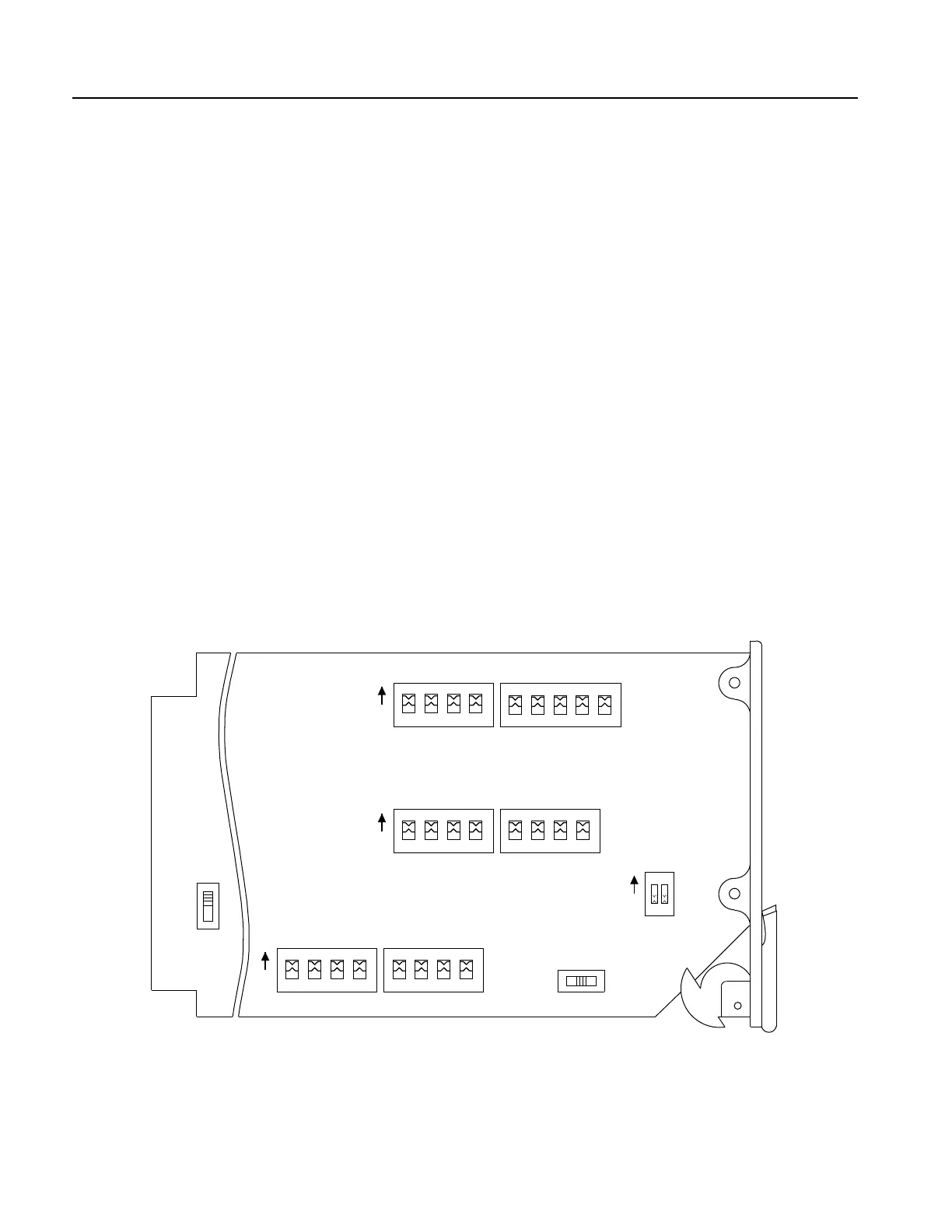
The following options provided by the unit allow flexibility of application. These options
are selected by setting switches on the pc board and front panel. Switch locations are
shown in Figure 3. Detailed information for switch selection is given in Table 2.
Figure 3. 4TOLB-3L1 Switch Locations
.1 .2 .4 .8 1 2 4 8 16
TRMT ATTN S2S1
IN
.25 .5 1 2 4 8 16 G
IN
GAIN (G) / LOSS (L)
S8
S7
.1 .2 .4 .8 1.5 3 6 12
IN
RCV ATTN S3S4
S6
RT
D4/COT
SEALING CURRENT
S5
SINK SRCOFF
IN
S9
20 MIN
TONE
4
NOTE: UNITS ARE SHIPPED WITH ALL ATTENUATION SWITCHES SET TO THE IN POSITION.
L