17
4TOLB-3L1
1306, Issue 2, May 1992
External LB (K3) Relay Contact
The normally closed LB relay contact, which internally connects TEK5, pin 46 (D4/COT
mode) or pin 52 (RT mode), and TEK6, pin 48 (D4/COT mode) or pin 49 (RT mode),
opens during loopback operation. The TEK5 and TEK6 leads can be used to disable an
externally connected modem.
Remote Testing
When the unit is in loopback mode, the transmit and receive ports (T, R, T1, and R1 leads)
are disconnected. The sealing current is also disabled. The transmit and receive paths are
internally connected through the gain/loss network so that the unit can be tested from the
far end. The gain/loss network is configured to maintain the transmission level point at the
transmit TLP and beyond during loopback. The front-panel LB indicator glows whenever
the unit is in the loopback mode.
5. SPECIFICATIONS
Table 3 lists the electrical and physical characteristics of the unit.
6. MAINTENANCE
The channel unit is composed of solid-state circuits. No routine maintenance is required to
keep the unit operating properly. In case of equipment malfunction, use the test card
(standard AT&T P6AD cord or Pulsecom B105097 adapter) and measurements of input
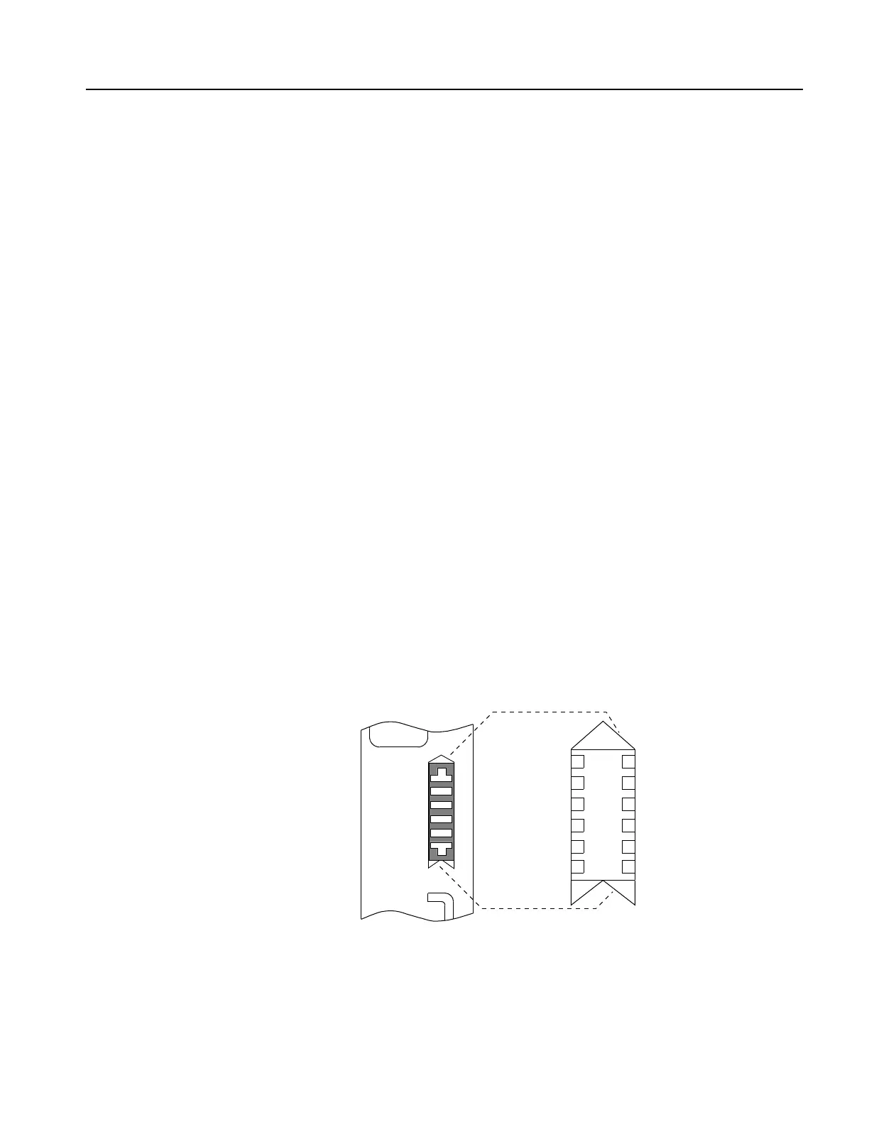
and output signals to determine the trouble source. The TEST jack provides access to the
TRMT TLP, the RCV TLP, and the T and R leads; it also provides a means of removing
the RNDIS RCV disable signal. See Figure 9.
Figure 9. 4TOLB-3L1 Test Points
7
8
9
10
11
12
1
2
3
4
5
6
TRMT
FILTER
TRMT
ATTN
NC
TPU CKT
NC
RCV
FILTER
GND
RCV ATTN
CHAN.
LOGIC
NC
NC
TRMT
GND
RNDIS
RCV
T
E
S
T
NC