4TOLB-3L1
1306, Issue 2, May 1992
16
B. VF Receive Operation
At the proper channel time, when the RSP(N), RSQ(N), and RWD leads are all at logic
one, the receive sampling gate closes to receive a sample at the receive input port (leads
RPAM and RPAMG). This action is repeated at every frame (8000 times per second), thus
restoring the waveform from the received digital samples. The signals from the receive
input bits are presented to the receive filter. The filter, which has a low-pass characteristic,
provides an output impedance of 600 ohms and brings the signal to the required +4 TLP.
This level is accessible at the receive TLP TEST jack (J1-3/9).
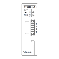
The front-panel TEST jack allows access to the receive voice path for test purposes. A test
card inserted into the J1 jack provides access to the output of the receive filter (terminal
J1-9) and the input of the receive attenuator (terminal J1-3).
Filtered VF signals are presented to the attenuator circuit, which provides from 0 to 24 dB
of attenuation in 0.1-dB steps. The attenuation switches are selected to obtain the
desired output level. Signals from the attenuator are routed through the receive
amplifier circuit and the transformer circuit to become available at the receive output port
(T1 and R1 leads).
C. Loopback Circuit
Activation
The LB circuit can be activated by one of three independent methods:
1) Tone Activation—The LB tone (2713 Hz) must be received at the receive input
RPAM for 2.5 seconds or longer and then removed to activate the loopback mode. LB
activation upon removal of the initial tone burst (rather than during) prevents
accidental looping at other LB points on a multi-point circuit. LB deactivation occurs
upon reception of a second LB tone of at least 0.6-second duration. Unlike LB tone
activation, the LB release sequence occurs during application of the tone. The first LB
tone will activate the LB circuit and start a timer. The electronic timer will time out
and the unit will return to the normal, non-looopback condition if the LB deactivation
tone is not received within either 4 or 20 minutes (depending upon the setting of
switch S9).
2) Manual Activation—Place the LB MAN switch accessible from the front panel in the
ON (up) position to force the module into the LB mode. Return the switch to the OFF
(down) position to release the module from this mode.
3) Local Activation—External connection of LOCAL LB lead, pin 45 (D4/COT mode)
or pin 25 (RT mode), to pin 19 (LOCAL LB GND lead) or pin 23 (PSC-96 RT)
activates the LB circuit. In the D4 mode only, this connection may be controlled by
either a switch or a relay contact.