EasyManua.ls Logo

Purelogic PLD880 - User Manual

Purelogic PLD880
10 pages
Print Icon
To Next Page IconTo Next Page
Loading...
01. General information
02. Delivery set
03. Technical features
04. Driver installation and ventilation
04. Driver functional capabilities
05. Control Signal Connections to the driver
06. Current and power option
07. Stepper motor connection to the driver
08. Protection functions, setup
09. Step division option
10. Terms of Warranty
INSTRUCTION MANUAL
2
2
3
5
6
7
10
11
13
14
15
PLD880
Stepper motor driver
Question and Answer IconNeed help?

Do you have a question about the Purelogic PLD880 and is the answer not in the manual?

Overview

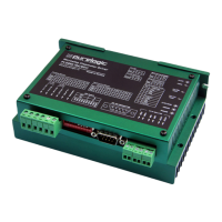
The PLD880 is a microstepping stepper motor driver designed by Purelogic R&D. It is suitable for controlling bipolar and unipolar stepper motors, particularly Purelogic R&D's PL86 series, but can also work with other stepper motors.

Function Description

The PLD880 driver operates with standard STEP/DIR/ENABLE control protocols. It features optoisolated control inputs compatible with 2.5V, 3.3V, and 5V logic levels. The device includes several built-in protections and functionalities:

  • Coil Short-Circuit Protection: Safeguards against short circuits in the motor coils.
  • Back EMF Effect Protection: Protects against voltage spikes generated by the motor.
  • Automatic Compensator of Normal Speed Stepper Motor Resonance: Reduces vibrations at mid-frequencies (6-12 cycles per second).
  • Phase Current Change Scheme with Frequency Increase (Morphing): Transitions from microstep to step mode with increasing frequency to ensure smooth operation.
  • Polarity Reversal Power Protection: Prevents damage if the power supply polarity is reversed (the driver will not switch on).
  • Soft Starter Scheme: Gradually increases current in stepper motor coils upon power-on or ENABLE signal activation, preventing sudden jolts.
  • STEP Inbuilt Frequency Generator: Allows for testing the driver without a PC or external generator, with frequency adjustable via the FREQ potentiometer.
  • AUTO-SLEEP Mode: The driver automatically enters rotor hold mode (full/half operating current) after 1 second of standstill (lack of STEP signal) to reduce heating. The coil current in AUTO-SLEEP mode is set by DIP-switch SW5.
  • Discrete Regulation of Operating Current: Allows for precise adjustment of stepper motor phase currents using DIP-switches (SW1, SW2, SW3, and multiplier factor SW4).
  • Phase Current Adaptation (Smooth Running): Adjustable via the PHASE TRIM potentiometer to reduce vibrations and uneven stepping at low revolutions.
  • Inbuilt Dumper: A back EMF compensation device from the stepper motor.
  • Optoisolated Output of Driver Alarm Signal: Provides an alarm signal, duplicated in the DB-9M connector.
  • Convenient Connectors: Features dismountable clip connectors for the stepper motor, power source, and control signals.
  • DB-9M Connector: Duplicates STEP/DIR/ENABLE/ALARM signals for convenient connection to PLC4x-G2.

Important Technical Specifications

  • Module Power Supply: 18...80V (bogey value 75V).
  • Operating Current of Stepper Motor Driver: 2.3...8A (discrete adjustment, see Fig. 2 in manual).
  • Step Division (Microstep): 1:2, 1:4, 1:8, 1:16, 1:32.
  • STEP Inbuilt Generator Frequency: 600...3,000 Hz.
  • STEP Max Signal Frequency: 270 kHz.
  • Max Shaft Rotation Frequency: 42 cycles per second or 2530 cycles per minute (tested with PL86H113, 75V, step division 1:32, 270 kHz).
  • Isolation Resistance: 500 MOhm.
  • Operating Temperature: 0...60 °C.
  • Unit Weight (without packaging): 0.6 kg.
  • Control Signal Characteristics (STEP/DIR/ENABLE):
    • Working voltage: 2.5V, 3.3V, 5V (may require extra current-limiting resistor).
    • Current consumption: up to 20mA.
    • Min STEP signal duration: 2ms.
    • DIR action time: 200 nsec before/after STEP front edge.
    • ENABLE action time: 100 ms.
    • Logic unit (voltage applied to input) for ENABLE: driver is off, coils are cut off.
    • Zero for ENABLE: driver is on, coils are supplied.

Usage Features

  • Power Off Before Changes: Always power off the device before making any connections or changing mode operations.
  • Power Switch Placement: The power switch should be installed before the power supply, at the ~220V side, not on the driver power line.
  • Connection Type: Only 'star' connection is allowed for multiple drivers; do not connect drivers in series.
  • Power Supply Polarity: Strictly observe the polarity of power supply and control signals connections. Do not connect the power supply's negative terminal to ground, mass, or housing.
  • Optimal Supply Voltage: Calculated as U = 32 * v (stepper motor phase inductance in mH), but not more than 80V.
  • Supply Current: Should be 50-70% of the claimed stepper motor coil current.
  • Phase Current Adaptation: Use the PHASE TRIM potentiometer to reduce vibrations. Start with the potentiometer at the extreme left (minimum value), then gradually adjust while observing motor behavior.
  • Stepper Motor Connection: Connect according to Fig. 2 (clips PH1.1[+A], PH1.2[-А] and РН2.1[+B], PH2.2[-B]). Note that swapping PH1.x and PH2.x phases will reverse motor rotation.
  • Wire Length: Wires leading to the stepper motor should not exceed 10 meters to avoid driver work failures. It is recommended to interlace stepper motor wires per phase and enclose them in a screened metal sheath, with sheaths and the stepper motor frame grounded.
  • Step Division: Electronically divides physical stepper motor steps into 2, 4, 8, 16, and 32 microsteps. This improves positioning accuracy and reduces resonances at low revolutions. Recommended divisions are 1:8, 1:16, or 1:32 for smoothest operation. Step division mode is set via DIP-switches SW6, SW7, SW8, and must be performed only when the driver supply is OFF.
  • Inbuilt STEP Frequency Generator: Can be activated by turning on SW10 to operate the driver with DIR/ENABLE signals and change step division without external control.

Maintenance Features

  • Environmental Conditions:
    • Working temperature: 0~45 °C.
    • Working humidity: 40~80% (non-condensing).
    • Storage temperature: -40~55 °C.
    • Storage humidity: lower than 80% (non-condensing).
    • Vibration: lower than 0.5G.
    • Avoid direct sunlight, oil mist, salt erosion, corrosive liquids, and gases.
  • Protection Functions:
    • Polarity Reversal Power Protection: Driver will not switch on if polarity is reversed.
    • Wrong Stepper Motor Coil Connection Protection: Protects against incorrect wiring or linked coils.
    • Voltage Jump Protection: Operates when voltage exceeds 90V, protecting against back EMF effects.
    • Softstarter: Gradually increases current to prevent sudden jolts.
    • Phase Current Adjustment: Helps eliminate vibrations at low revolutions.
    • Automatic Compensator: Removes mid-frequency resonance effects.
    • LED Indicators: Green LED POWER, green LED STEP/ENB, and red LED ERROR flash on power-up. Red ERR LED goes out in 1 sec if no alarm. Green STEP/ENB LED is on (if ENABLE=0) or blinks (with STEP frequency), or goes out (if ENABLE=1).
    • Alarm Indication: When a protection function operates, the driver switches off motor coils, the red ERR LED flashes, the green STEP/ENB LED goes out, and the opto-coupler of error closes/opens. The opto-coupler's collector (C) and emitter (E) are terminated to the DB-9M connector. SW9 (Function) inverts the opening/closing of the opto-coupler error.
    • Restoration: The driver restores operation after the alarm cause is removed and power supply is switched off/on.

Warranty Terms

  • Warranty Period: 12 months after purchase, valid only if operational conditions and scheduled maintenance are strictly followed.
  • General Terms:
    • Seller guarantees the working ability of individual components but does not assume responsibility for the quality of their joint work if purchased as separate components.
    • Seller does not guarantee compatibility with products already owned by the buyer or bought from third parties.
    • Product components and configuration may change without notice due to continuous technical improvement.
  • Warranty Acceptance Conditions: Product must be returned in the same complete set as purchased.
  • Warranty Service Procedure: Service involves testing the claimed defect. If the defect is proven, warranty repair is carried out.
  • Exclusions: Warranty does not cover glass, electric lamps, starters, and expendable materials, nor damage caused by:
    • Inappropriate transport or storage conditions.
    • Wrong connection or operation in abnormal/off-design mode.
    • Conditions outside manufacturer-supplied temperature and humidity limits.
    • Third-party circumstances (voltage jumps, natural disasters).
    • Mechanical or thermal damages.
    • Traces of foreign objects (dust, liquids, insects) or extraneous inscriptions.
    • Unauthorized tampering or repair (opening, home-made soldering, component changes).
    • Self-diagnostic function showing improper exploitation.
    • Assembly, integration, and start-up not performed by Seller specialists or recommended organizations (unless regulated by goods documentation).
    • Exploitation under power supply conditions not meeting manufacturer's requirements, or without an electrical protection device.
    • Resale of the product to a third party by the initial buyer.
    • Defects caused by low-quality spare parts, expired spare parts, consumable materials, or using spare parts/consumable materials not corresponding with manufacturer's requirements.

Purelogic PLD880 Specifications

General IconGeneral
BrandPurelogic
ModelPLD880
CategoryControl Unit
LanguageEnglish