Edition from 23.11.2017
11
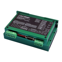
PLD880. Stepper motor driver
www.purelogic.ru8 (800) 555 63 74
07. Current and power option
Fig. 4. Purelogic R&D stepper motor connection to the driver
PLD880 driver is optimal for control of bipolar and unipolar stepper
motors Purelogic R&D series PL86.
Stepper motor connection to the driver is performed as it is shown in
fig.2 (clips PH1.1[+A], PH1.2[-A] и PH2.1[+B], PH2.2[-B]).
The driver has protection against wrong stepper motor coil connection
and coils linked together / ‘+’ power supply.
Purelogic R&D stepper motor connection to the driver is performed
according to fig. 4.
Please note in case of changing phases PH1.x<>PH2.x, the motor
will start rotating in the opposite direction (inversion analogue of DIR
signal).
The length of wires leading to the stepper motor from the driver must
not exceed 10 meters. Longer wires can lead to driver’s work failures.
It is strongly recommended to interlace the stepper motor wires per
phase, then put this braid to the screened metal sheath. Sheathes and
stepper motor frame must be grounded.
PH1.1 [+А] Red (RED)
PH1.2 [-А] Orange (ORG)
PH2.1 [+B] Blue (BLU)
PH2.2 [-B] Green (GRN)
Stepper motor connection to the driver
08
Max supply voltage driver option depends on the applied stepper motor
and desired max rotation speed. Optimal supply voltage calculation
for the stepper motor is carried out according to the formula U=32*v
(stepper motor phase inductance mH), but not more than 80V.
Supply current must be chosen 50...70% from the claimed stepper
motor coil current.
Working current setting is performed by DIP-switches (current value is
set up by SW1, SW2, SW3 and multiplier factor SW4).
Phase current adaptation (stepper motor smooth running) is carried
out by PHASE TRIM potentiometer when vibrations and uneven stepping
at low revs is found.
Adaption strategy is as follows:
1) A potentiometer is set to the extreme left position (minimum value).
2) Stepper motor is connected, voltage is supplied, vibration frequency
is set up by STEP frequency generator.
3) PHASE TRIM potentiometer moves to ¼ while rotating PH2(A) TRIM ,
the vibration reduces.
If there are still vibrations, PH1(A) TRIM potentiometer moves to ¼
again, rotating PH2(A) TRIM, the vibration reduces, etc. You may fail to
reduce vibrations totally because of stepper motor specifics.
When there is no STEP signal for more than 1 sec, the driver goes to
AUTO-SLEEP mode and reduces the coil current to the value identified
by DIP-switch SW5.
POWER OFF DEVICE BEFORE MAKING ANY SWITCH-OVERS.
07
Current and power option
 Loading...