Edition from 23.11.2017
7
PLD880. Stepper motor driver
www.purelogic.ru8 (800) 555 63 74
05. Driver functional capabilities
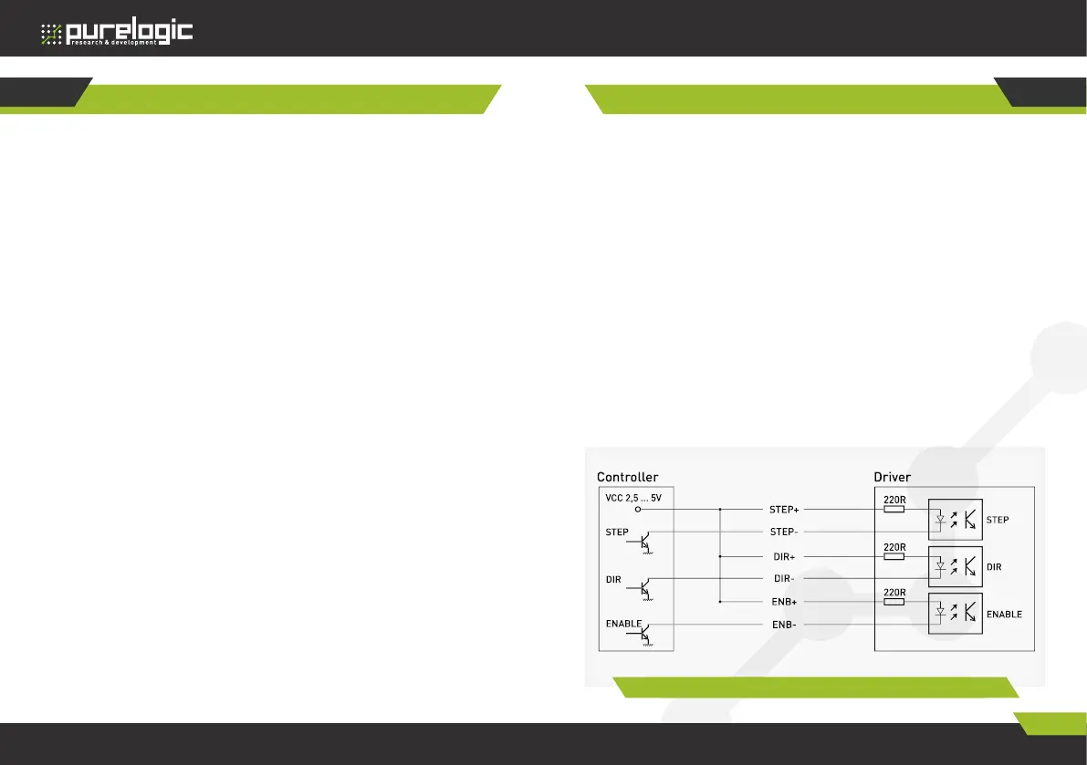
The driver operates with standard signals STEP/DIR/ENABLE.
The signals are transmitted to differential optoisolated inputs.
The scheme of differential input device and connection method to the
controller with outputs ‘open collector’ type is shown in fig.2.
STEP signal characteristics — working voltage 2.5V, 3.3V , 5V (you may
need extra current-limiting resistor connection), current consumption
up to 20mА, min signal duration is 2ms. The step is carried out on the
signal front edge.
DIR signal characteristics — working voltage 2.5V, 3.3V, 5V (you may
need extra current-limiting resistor connection), current consumption
up to 20мА, action time is 200 nsec before/after front edge STEP.
ENABLE signal characteristics — working voltage 2.5V, 3.3V, 5V
(you may need extra current-limiting resistor connection), current
consumption up to 20mА, action time is 100 ms. Logic unit (voltage is
applied to the input) – stepper motor driver is off and coils are cut off
the current, zero – stepper motor driver is on and stepper motor coils
are supplied.
Fig. 2. Differential input device
Control Signal Connections
06
05
Driver functional capabilities
• Optoisolation of module control signals STEP/DIR/ENABLE.
• Expanded discrete adjustment of working current in stepper motor
coils.
• Stepper motor softstarter. After turning on the power or ENABLE
signal, current is increasing gradually in stepper motor coils. This
allows to exclude typical bump when turning stepper motor on.
• AUTO-SLEEP mode, driver after 1 sec standstill (lack of STEP signal)
automatically enters rotor hold mode (full/half operating current) for
heating reduction.
• Coil short-circuit module protection, wrong stepper motor connection
protection.
• Over-voltage protection (back EMF effect protection).
• Polarity reversal supply voltage protection (the driver will not be
switched ON).
• Inbuilt automatic compensator of midfrequency stepper motor
resonance.
• Phase current adjustment for vibrations exclusion at low revs.
• Modifications scheme of phase current form with frequency increase
(morphing, transfer from microstep to step mode with with frequency
increase).
• Inbuilt dumper (back EMF compensation device from stepper motor).
• Inbuilt STEP generator frequency (test driver start can be performed
without PC or external generator connection).
• Optoisolated output of driver alarm signal.
• Convenient dismountable clip connectors to step motor, power source
and control signals.
• Alarm indication supplied by STEP/ENABLE frequency, inbuilt dumper
operation.
• STEP/DIR/ENABLE/ALARM signals are duplicated in DB-9M type
connector for convenient connection to PLC4x-G2.
 Loading...