Helm Systems
2-3
Section 2
C280 / S280 / C310 / ST310
2.6 Steering System
The steering system is hydraulic and made
of two main components: the helm assembly
and the hydraulic cylinder. The helm unit
acts as both a fluid reservoir and pump.
Turning of the helm, or steering wheel,
pumps the fluid in the hydraulic hoses and
activates the hydraulic cylinder causing the
motors to turn. A slight clicking sound may
be heard as the wheel is turned. This sound
is the opening and closing of valves in the
helm unit and is normal. Refer to the steer-
ing manufacturer owner’s manual for spe-
cific information on the steering system.
Dual engine outboards are coupled at the til-
ler arms by a tie bar. The outboards must be
aligned with each other to provide maximum
stability on straight ahead runs and proper
tracking through corners. If damage has
ever occurred with the outboards or steering
system, the outboards may have to be
realigned.
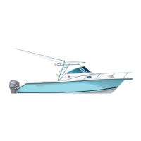
Power Steering (Optional)
The power steering system uses an electri-
cally controlled hydraulic pump to provide
power to the standard hydraulic steering
system. Additional components are a helm
mounted power steering switch and a
hydraulic pump. The switch activates the
power steering feature. Manual steering is
always available regardless of the switch
position. To reduce the sensitivity of the
steering, turn off the power steering at low
speeds. To conserve battery power, because
of limited engine charging output during
extended periods of slow speed operation,
the power steering should be turned off.
Refer to the Teleflex® Power Assist manual
for more information.
Tilt Helm
A tilt helm, steering wheel may be installed
on your boat. To tilt the helm, depress the
lever located in the base of the helm and
lock into position. DO NOT adjust when the
boat is underway.
2.7 Trim Tabs
The trim tabs are recessed into the hull on
the transom. Switches are used to control
the trim tabs. The switches are labeled and
control bow up and down movements. They
also control starboard and port up and down
movements. Bow up and bow down will con-
trol the hull planning attitude, while port and
starboard up and down provide control for
the hull trim side to side.
Before leaving the dock, make sure that the
tabs are in the full “UP” position by holding
the control in the bow "UP" position for ten
seconds. Do not continue to operate the
switch when the tabs are fully up or down.
Establish the intended heading and cruise
speed before attempting to adjust the hull
attitude with the trim tabs. Always make
slight adjustments to reduce over adjust-
ments. After stabilizing speed and direction,
move the trim tabs to achieve a level side to
side running attitude being careful not to
over trim.
After depressing a trim tab switch, always
wait a few seconds for the change in the trim
plane to take effect.
! CAUTION
Some autopilot systems have engine
position sensors mounted to the
hydraulic steering cylinder. The sen-
sor bracket can contact the transom
when the engines are fully tilted up
and damage the autopilot, engine rig-
ging or transom. Monitor the bracket
and rigging while engines are tilting to
determine the best position for your
application.
Engine Stop Switch (Typical)