Please note: If charging two batteries that are interconnected on the
same circuit (eg in parallel) only connect one battery to ‘Battery 1’ and
do not connect the second battery to ‘Battery 2’. Battery 2 connection
is only for charging a completely separate circuit with a battery on.
Forexampletheenginebatteryofamotorhome.
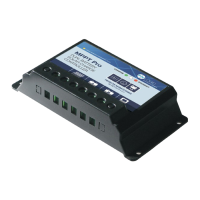
PRODUCT FEATURES
(1)
Solar charging status
LED indicator
(2) Solar module terminals,
connect solar module
(3) Battery terminals,
connect to battery 1
(4) Battery terminals,
connect to battery 2
(5) Remote display connection.
INSTALLATION INSTRUCTIONS
NOTE: When mounting the
controller, ensure free air through
the controller heat sink (back plate).
There should be at least 6 inches
(150mm) of clearance above and
below the controller and 3 inches
(75mm) each side to allow for
cooling. If mounted in an enclosure,
ventilation is highly recommended.
WARNING: Risk of explosion!
Never install the controller in a sealed
enclosure along with batteries! Do
not install in a confined area where
battery gasses can accumulate.
1. Choose Mounting Location. Locate the controller on a vertical surface
protected from direct sun, high temperature and water.
2. Check for Clearance. Place the controller in the location where it will
bemounted.Verifythatthereissufcientroomtorunwiresandthat
there is sufficient room above and below the controller for air flow.
3. Mark and Drill Holes. Use a pencil or pen to mark the four mounting
hole locations on the mounting surface and drill pilot holes.
4. Secure Controller. Place the controller on the surface and align the
mounting holes with the drilled holes in step 3.
5. Secure the controller in place using self tapping screws
(not supplied).
(150mm)
(150mm)
(75mm)
(75mm)
(1)
(2)
(5)
(3) (3)