WIRING
WARNING: Risk of explosion or fire! Never short circuit battery positive
(+) and negative (–).
WARNING: Risk of electric shock!Riskofelectricshock!Exercisecaution
when handling solar wiring. The solar module(s) high voltage output
can cause severe shock or injury. Cover the solar module(s) from the sun
before installing solar wiring.
When installing a fuse and holder, make sure that the distance between
the fuse holder and the positive terminal of battery is at most 150mm.
Only install a fuse holder when setting up. Do not insert a fuse at this time.
Thecontrollercanaccept12Vor24Vnominaloff-gridsolarmodule(s).
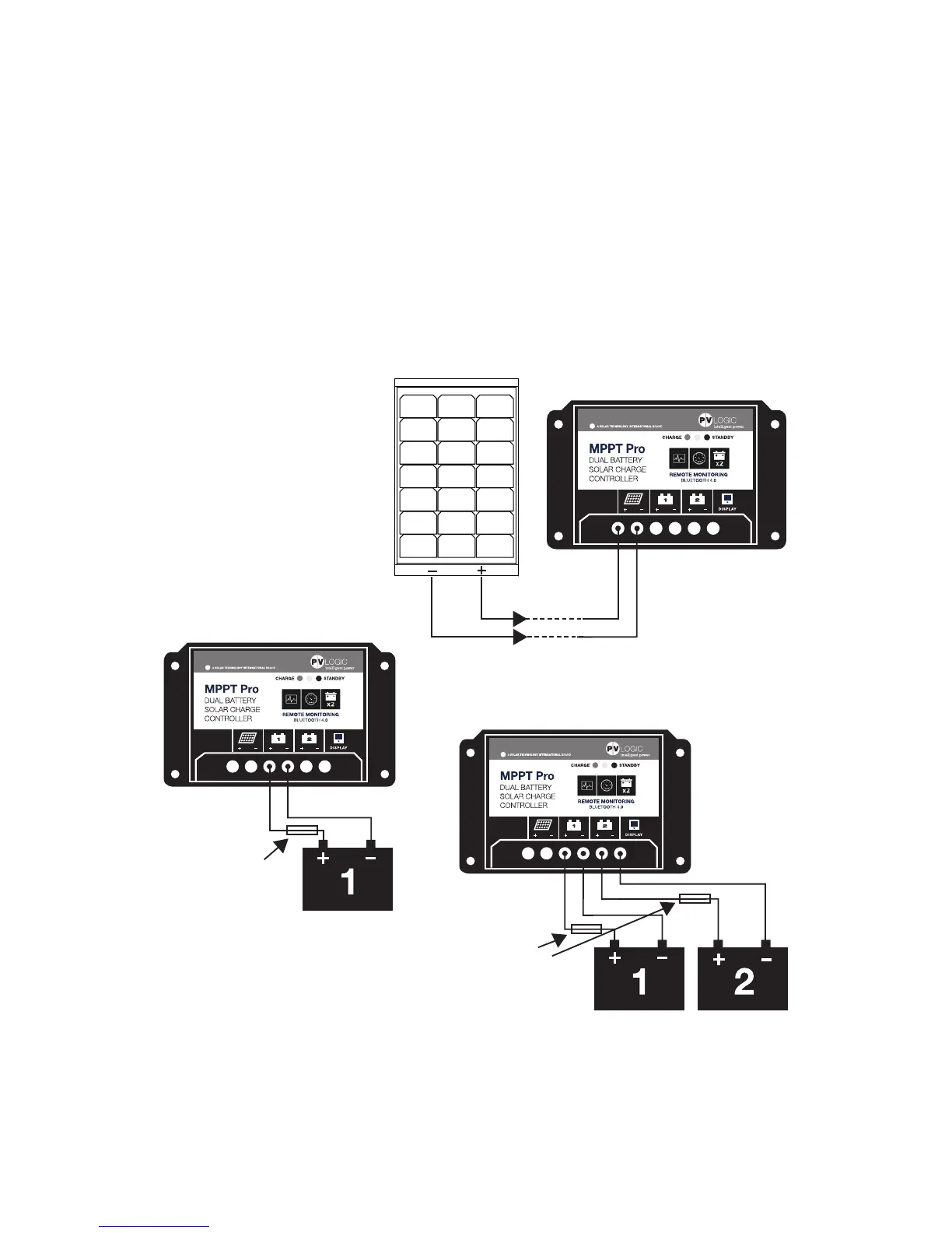
Solar connection
Connect the + and –
from the solar panel to
the solar inputs on the
charge controller.
Battery connection 2 (optional)
Connect the + and – from the 2nd
battery via a fuse (with fuse removed)
to the ‘Battery 2’ output on the
charge controller.
CHARGE CONTROLLER
SOLAR PANEL
CHARGE CONTROLLER
BATTERY
20 AMP
IN-LINE FUSE
(NOT PROVIDED)
Battery connection 1
Connect the + and – from
the 1st battery via a fuse
(with fuse removed) to the
‘Battery 1’ output on the
charge controller.
CHARGE CONTROLLER
BATTERIES
20 AMP
IN-LINE FUSE
(NOT PROVIDED)