
N
Nicole MooreJul 29, 2025
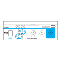
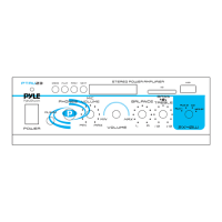
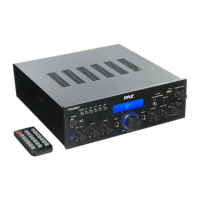
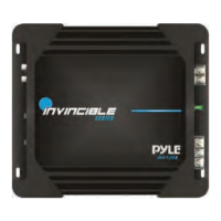
What to do if my Pyle Invincible is turning off at medium to high volume?
- MMichael ScottJul 30, 2025
If your Pyle Amplifier is turning off at medium to high volume, it's crucial to check the speaker load impedance. Ensure that you are using the correct speakers to meet the recommended impedance. Keep in mind that DC resistance and AC impedance might differ if you're using an Ohm meter to check speaker resistance.