The slave battery’s address will be assigned automatically. 1 master battery can supervise 7
slave batteries (maximum 8 batteries in each battery group). Multiple battery groups should
setup the master batteries’ ADD switch. (Refer to Chapter 4 / D)
Dip2 Dip3 Dip4 Group Address Number
0 0 0 0
th
: Single battery group’s master battery should setup as this.
1 0 0 1
st
: 1
st
battery group’s master battery should setup as this.
0 1 0 2
nd
: 2
nd
battery group’s master battery should setup as this.
1 1 0 3
rd
: 3
rd
battery group’s master battery should setup as this.
0 0 1 4
th
: 4
th
battery group’s master battery should setup as this.
1 0 1 5
th
: 5
th
battery group’s master battery should setup as this.
0 1 1 6
th
: 6
th
battery group’s master battery should setup as this.
1 1 1 7
th
: 7
th
battery group’s master battery should setup as this.
Console
Console Communication Terminal: (RJ11 port) follow RS232 protocol (Baud Rate: 1200), for
manufacturer or professional engineer to debug or service.
CAN
CAN Communication Terminal: (RJ45 port) follow CAN protocol (Baud Rate: 500K), for output
batteries information.
RS485
R485 Communication Terminal: (RJ45 port) follow RS485 protocol (Baud Rate: 9600 or115200),
for output batteries information.
Link Port 0, 1
Link Port 0, 1 Communication Terminal: (RJ45 port), for communication between multiple
parallel batteries.
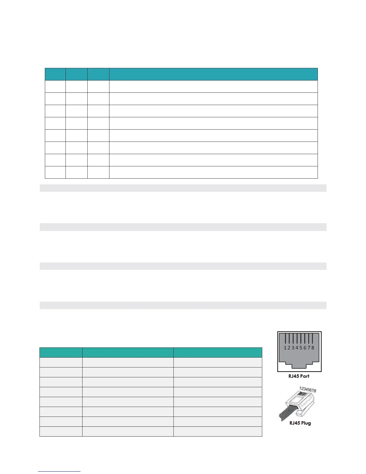
Definition of RJ45 Port Pin
No. RS485Pin CAN Pin
1 -- --
2 -- GND
3 -- --
4 -- CANH
5 -- CANL
6 GND --
7 RS485A --
8 RS485B --
6 / 23 18BQSV0801