+44(0)333 444 1280 (UK) customer.support@pyronix.com (UK) www.pyronix.com Pyronix Limited, Pyronix House, Braithwell Way, Hellaby, Rotherham, S66 8QY, UK
Tri-detection method
2 digital dual-element passive IR & 1 microwave
doppler unit
Sensitivity
AUTO or HIGH
Temperature compensation
Digital
Pet immunity
Up to 24kg, 1m high
Detection speed
0.25 - 2.5m/s
Tri-masking
Adjustable from 0m to 1m, covers all 3
technologies
Casing
3mm polycarbonate, 0.4mm HDPE in Lens Area.
IP Rating: IP55
Lenses
UV compensated
Operating voltage & current
9 - 16V DC, (24mA @ 13.8V DC quiescent)
Relay output
3 x SELV limits, 60V DC 50mA (42.4V AC peak)
Mounting height & range
1m - 1.5m = 12m range
Tamper switches
12V DC 50mA both front and rear
Temperature
Storage: -40°C to 80°C
Operating: -30°C to 70°C
Dimensions & weight
188 x 77 x 84mm, 0.3kg
Product information
Applies to electrical products sold within the European community. At the end of the electrical product’s life,
do not dispose of it with household waste. Where possible, recycle the product. Check with your Local
Authority or retailer for recycling advice in your country.
Warranty
This product is sold subject to our standard warranty conditions and is warranted again defects in
workmanship for a period of five years (excluding lens). In the interest of continuing care and design, Pyronix
Ltd reserves the right to amend specifications without giving prior notice.
Environmental Class (EC) IV
9.9GHz: AT, BE, CH, CY, CZ, DK, EE, FI,
FR, GR, HR, HU, IE, IS, IT, LT, MT, NL,
PL, PT, SI, TR, UAE
10.525GHz: BE, CH, CY, DK, ES, HU, IE,
IS, IT, MT, MY, NL, NO, SE, SI, UAE, USA
10.587GHz: GB, MY
EN
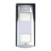
XDL12TT-AM
RINS1900-1
1. Installation
Scan the QR code for fixing instructions and adapter information. Ensure that the detector is
installed away from reflected sunlight and large objects.
2. Switches
If you disable the detector’s LEDs, you can remotely enable them in walk tests. Connect the
detector’s LED terminal to a control panel PGM output that switches to 0V to enable the LEDs.
3. Microwave range and angle of detection
Use the highlighted dials to change the microwave range and angle of detection.
4. LEDs
Four LEDs show the status of the detector.
5. Lens inserts
Use lens inserts to control coverage.
6. Header pins
Place two-pin jumpers onto header pins to adjust resistance for alarm, masking/fault and tamper.
7. Anti-masking
Anti-masking triggers an alarm when part or all of the sensor is masked by an intruder. Use the
highlighted dial to change the masking area range. When an intruder enters the masking area,
LED2 pulses. When the intruder moves out of the masking area, if the detector does not see
activation on all 3 sensors within 1 min, the mask/fault relay opens and LED1 and LED3 turn on.
To reset, remove the obstruction and perform a walk test for 1 min.
8. Blocking
Blocking detects intruders behind objects when the panel is disarmed. To use blocking, move
switches 3 and 4 down, and connect the R1 input to a panel output that is negative when
disarmed. When blocking is active, the alarm relay opens and LED1 and LED3 turn on. To reset,
perform a walk test.
9. Connecting to CCTV and lights
To connect the detector to CCTV and lights, refer to the wiring diagram.
Specifications
4m 8m 12m
1-1.5m
1-1.5m
< 24kg
1m
4m 8m 12m
1-1.5m
< 10m
4m 8m 12m
1-1.5m
> 10m
4m 8m 12m
ON
LED 1 LED 2 LED 3
LED 4
Top PIR activated
Bottom PIR activated
Microwave activated
Alarm
Powering up
Low voltage
Top PIR failed self-test
Bottom PIR failed self-test
Microwave failed self-test
Masked / blocked
Mask processing
12m
1.3m
1.3m
~8m
0m
12m
12m
12m
1-1.5m
1
2
3
2
4
5
1-1.5m
4m 8m 12m
Switch
1
2
3
4
5
6
7
8
Up (ON position)
AC 230V, 50 Hz
Anti-masking always on
Blocking off
R1 off
Auto sensitivity
Open mask & alarm relays
Buzzer on
LEDs on
Down
AC 110V, 60 Hz
Anti-masking on when disarmed
Blocking on when disarmed
R1 on
High sensitivity
Open mask relay only
Buzzer off
LEDs off
2
2