10 11
CHAPTER 2 CONNECTIONS AND CONTROLS
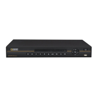
2.1 FRONT PANEL
CONNECTIONS AND CONTROLS
CHAPTER 2
PICTURE 2-1
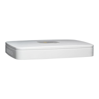
PICTURE 2-2
1 2
6 7 98
3 4 5
1 2
7 8
3 4 5 6
Number Item Function
1
Function
Button
Single Channel Viewing Mode: Opens Color Adjustment
Virtual Keyboard: Backspace function
2 IR Sensor Infrared Receiver for Remote Control
3 Escape Button Exit any menu or current operation
4 Enter Button
Viewing Mode: Go To Menu
In Menu: Acts as mouse click
5
Directional
Buttons
Navigate through menus.
Change selections in pull down menus (Up/Down buttons)
Toggle settings (Up/Down buttons)
6 Power Button Puts DVR into Standby mode or wakes it up.
7 Status Lights
Alarm: Not functional on this model
Net: Red light indicates that network connection is lost
HDD: Red light indicates that hard drive is operating
Power: Red light indicates that DVR is powered up
8 USB Port
For use with flash drive when backing up or updating
firmware. Not for use with mouse.
2.2 REAR PANEL
Number Item Function
1 Video In Ports BNC Connectors for video feed from cameras (4)
2 Audio In BNC Connectors for audio feed from microphones (2)
3 Audio Out BNC Connector for audio output
4 USB Port USB port for mouse
5 Power Switch
Turns DVR on or off. Use Shutdown menu function or front
panel power button before switching off.
6 Video Out BNC Connector to television
7 Network Ethernet cable connection to network
8 VGA Video Out To connect to a VGA monitor (19” or larger)
9 Power Input Connect 12V DC power supply here
 Loading...