Both bars must t
between the lowest horizontal frame rails
of the wheelchair. Always cut an equal
amount from both ends and allow the
cross bar to reach the oval openings of the
bracket clamps.
Slide the four
bracket clamps onto the cross bars and
place cross bars between the frame rails
making sure the holes on the cross bars
are on top. Now slide the clamps out unl
the tubing is rmly seated in the radius of the clamp. Mark your holes to be drilled onto the cross bars.
to the cross bars. Posion the assembly so that the docking bolt is
approximately 2” in front of the wheel axis. Mark your holes and excess to be drilled/cut.
Make sure that there is at least 3-4” of clearance
above the V bracket and that it is scking out far forward enough to clear any foot rests, covers, and/or
obstrucons (see diagram below). Mark your holes and excess to be drilled/cut.
Hole sizes are as follows:
• Center Strap: 3/8” holes (four locaons)
• Cross Bars: 5/16” holes (two locaons per bar)
• Bracket Clamps: 5/16” holes (two locaons per clamp)
• V Bracket Stabilizer: 3/8” holes (two locaons)
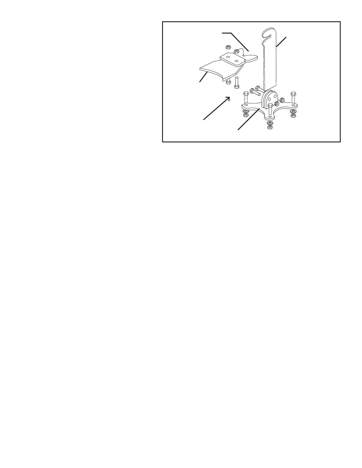
Secure Center Strap to cross bars with 3/8” hardware provided, as
well as the V Bracket on the front. Use the 5/16” hardware to secure the bracket clamps to the frame
of the wheelchair and also to the cross bars. Aach the docking bolt to the bracket on the boom of
the wheelchair. Adjust the height of the docking bolt by threading or un-threading it into the center
strap. Final height should be determined with user sing in the wheelchair. Review diagram on right
for installaon of the stabilizer base.
V-GUIDE
WHEELCHAIR
BRACKET
STABILIZER
ARM
STABILIZER BASE