Do you have a question about the QMTECH XILINX SPARTAN-7 and is the answer not in the manual?
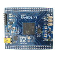
Introduces the QMTech® Spartan-7 Core Board, its features like MicroBlaze processor, DDR3 support, and application suitability.
Details the scope of the user manual, covering the QM_Spartan-7 board and Xilinx Vivado 2018.2 setup.
Lists the key parameters and components of the QM_Spartan-7 development board.
Guides users through installing necessary software and hardware for the QM_Spartan-7 board, including Vivado and cables.
Explains how to program the FPGA using the Bitstream (*.bit) file or load the *.mcs file into the on-board SPI flash.
Details the 5V DC input and 3.3V supply indication for the QM_Spartan-7 board.
Details the 3.3V power supply circuit using the MP2359 DC/DC chip and recommended input voltage.
Describes the default boot sequence from SPI Flash and M0:M1:M2 settings.
Details the 50MHz system clock provided by an external crystal for the FPGA.
Explains the JTAG port connection using a 6P 2.54mm pitch header.
Shows the user LEDs and the 3.3V power supply indicator LED.
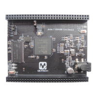
Describes the two 50P 2.54mm pitch headers for connecting external modules.
Illustrates the PROGRAM_B key and two user keys (SW1, SW2) on the board.
Details the CP2102-GMR USB to serial bridge chip and its hardware design.
| FPGA Family | Xilinx Spartan-7 |
|---|---|
| FPGA Model | XC7S50 |
| Flash Memory | 16 MB |
| USB | USB 2.0 |
| Power Supply | 5V DC |
| I/O Voltage | 3.3V |
| Logic Cells | 52160 |
| Ethernet | 10/100/1000 Mbps |
| Connectors | PMOD |