EasyManua.ls Logo

QOLSYS IQ GLASS-S User Manual

Default Icon
2 pages
To Next Page IconTo Next Page
Page #1 background imageLoading...
Page #1 background image
Sensor: 2.75”H x 3.88”W x 1.5”D
Compatible control panels: Qolsys IQ Panel 2
Frequency: 319.5MHz
Battery: 3V GP CR123A (x2)
Operating Temperature: 14°F to 122°F
Detection Range: 20ft Max and 5ft Min
Intended for use with IQ Panel 2
Supervisory signal interval: 70 min (approximately)!
Intended for use with 3/16” and 1/4” plate or tempered
glass.
SPECIFICATIONS
IQ GLASS S-LINE INSTALLATION MANUAL
Ceiling
Walls
Mounting Height:
The sensor should be mounted between 6.5ft and 8.5ft above the floor.
All protected glass must be within a clear line of sight of the sensor and
within the 20ft max range.
Ceiling mount
Wall mount
CHOOSE
INSTALLATION
LOCATION
IQ GLASS-S
Note: for UL/cUL listed the device
shall be secured using the provided
mounting screws.
STEP
2
STEP
3
DETACH
FACE
PLATE
STEP
4
STEP
5
REPLACE
FACE
PLATE
SECURE
TO
SURFACE
REMOVE
BATTERY
TAB
Place your panel in
autolearn" mode
Open and close the case
to “tamper” the device
Customize name and settings as
desired and touch “ADD”
ADD
STEP
6
LEARN
INTO
PANEL
Note: Detector LED will flash rapidly for 5
minutes as part of initial power up
sequence.
Note: For UL/CUL installations use this device only in conjunction
with compatible Qolsys wireless alarm system IQ Panel 2.
Question and Answer IconNeed help?

Do you have a question about the QOLSYS IQ GLASS-S and is the answer not in the manual?

QOLSYS IQ GLASS-S Specifications

General IconGeneral
BrandQOLSYS
ModelIQ GLASS-S
CategoryAccessories
LanguageEnglish

Summary

Specifications

Step 1: Choose Installation Location

Mounting Height and Range

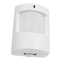
Sensor placement guidelines for optimal detection, between 6.5-8.5ft high, within 20ft range.

Step 2: Secure to Surface

Step 3: Detach Face Plate

Step 4: Remove Battery Tab

Step 5: Replace Face Plate

Step 6: Learn Into Panel

Step 7a: Testing Mode - Sensitivity

Sensitivity and Range Settings

Customize sensor sensitivity and detection range (20ft to 5ft) using dip switches.

Step 7b: Testing Mode - LED Indicator

LED Indicator Guide

Understand LED behavior for initial power up, test mode, and alarm events.

Step 7c: Testing Mode - Glass Break Simulation

Glass Break Simulator Test

Use FG-701 simulator to test sensor response to glass breaks, ensuring proper audio detection.

Related product manuals