18
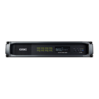
Main Analog Input Connector Pinout
25-pin male D-Sub to 25-pin male D-Sub
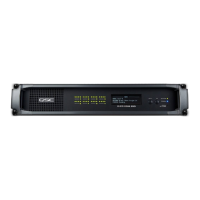
Auxiliary Analog Input (Surround EX) Pinout
25-pin male D-Sub to 25-pin male D-Sub
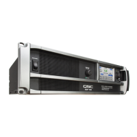
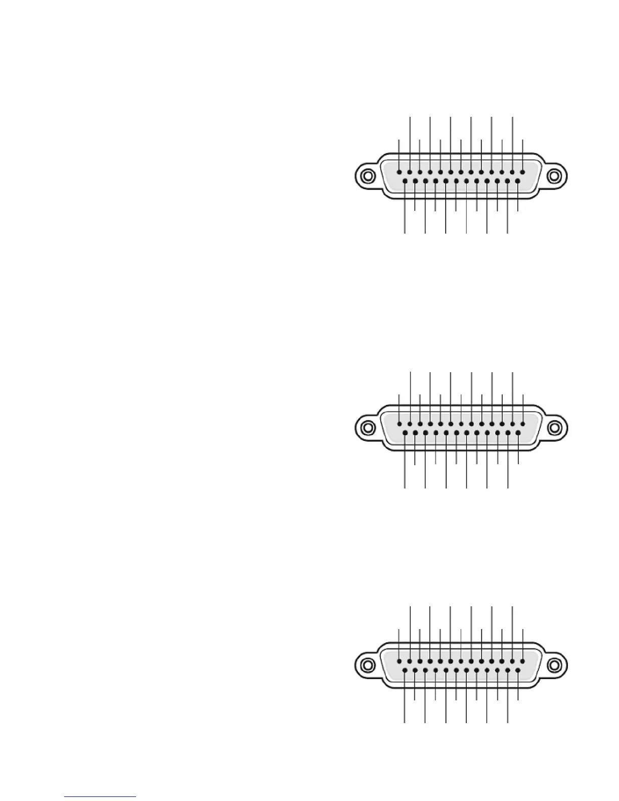
Digital (AES3) Input Connector Pinout
25-pin male D-Sub to 25-pin male D-Sub
Pin # Description Pin # Description
1 (not used) 14 Left extra +
2 (not used) 15 Left extra -
3 Back surr left - 16 Back surr left +
4 (not used) 17 (not used)
5 (not used) 18 (not used)
6 Back surr right - 19 Back surr right +
7 (not used) 20 (not used)
8 (not used) 21 (not used)
9 Right extra + 22 Right extra -
10 Surround left - 23 Surround left+
11 Surround right - 24 Surround right +
12 (not used) 25 (not used)
13 (not used) Shell Chassis ground
Pin # Description Pin # Description
1 AES 1: Gnd 14 AES 1: Pos
2 AES 1: Neg 15 AES 2: Gnd
3 AES 2: Pos 16 AES 2: Neg
4 AES 3: Gnd 17 AES 3: Pos
5 AES 3: Neg 18 AES 4: Gnd
6 AES 4: Pos 19 AES 4: Neg
7 (not used) 20 (not used)
8 (not used) 21 (not used)
9 (not used) 22 (not used)
10 (not used) 23 (not used)
11 (not used) 24 (not used)
12 (not used) 25 (not used)
13 (not used) Shell Chassis ground
Pin # Description Pin # Description
1 Chassis ground 14 Left -
2 Left + 15 Chassis ground
3 Left extra - 16 Left extra +
4 Chassis ground 17 Center -
5 Center + 18 Chassis ground
6 Right extra - 19 Right extra +
7 Chassis ground 20 Right -
8 Right + 21 Chassis ground
9 Chassis ground 22 Chassis ground
10 Surround left - 23 Surround left +
11 Surround right - 24 Surround right +
12 Subwoofer - 25 Subwoofer +
13 Chassis ground Shell Chassis ground
Main Analog Input
Auxiliary Analog Input
Digital Input
(the connector providing AES3 pairs 1-4 and the connector providing
AES3 pairs 5-8 are wired the same and with the same pair sequence)
12
11 7
10
13 9
8 6 4 2
5 13
24
23 19
22
25 21
20 18 16 14
17 15
12
11 7
10
13 9
8 6 4 2
5 13
24
23 19
22
25 21
20 18 16 14
17 15
12
11 7
10
13 9
8 6 4 2
5 13
24
23 19
22
25 21
20 18 16 14
17 15
 Loading...