3
TD-000449-00-C
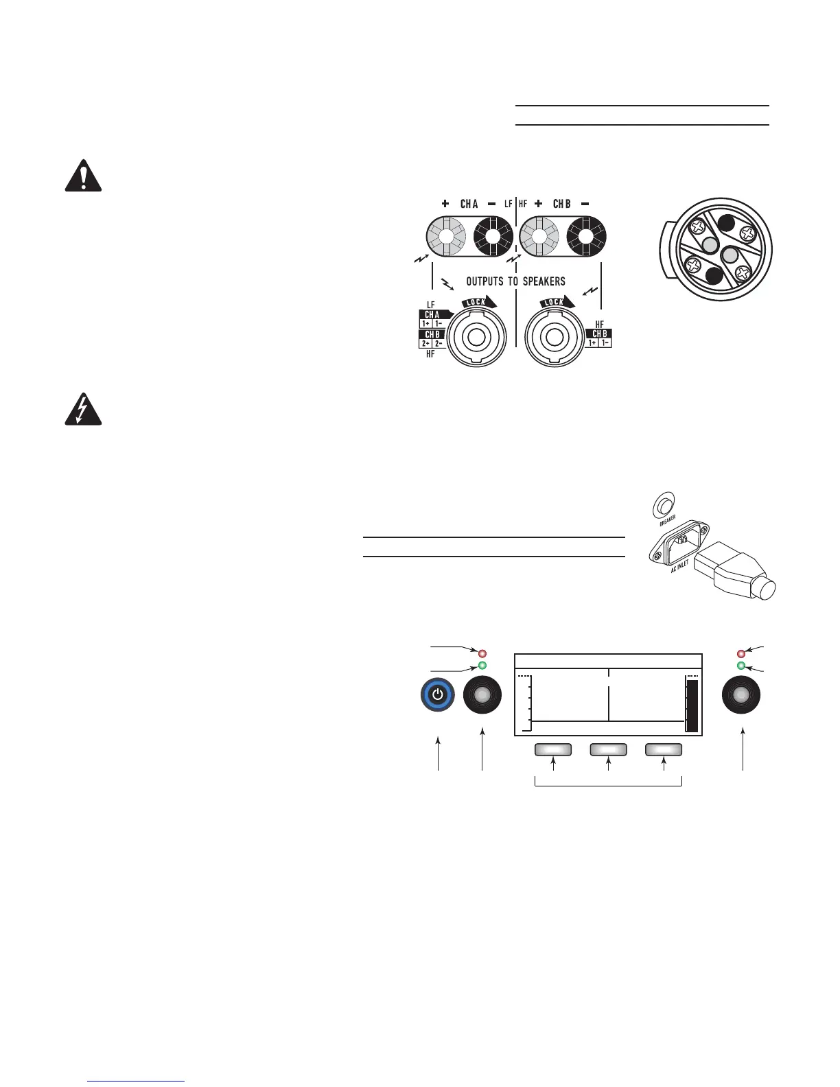
Outputs (Channels A & B)
See Figure 2
4 or 8 impedance
CAUTION!:
Do not combine the audio outputs in any way. Do not connect
the audio outputs to ground.
Wiring
Be sure to observe polarity.
• NL4 connector – See
Figure 3
• Binding Posts - Use banana plugs or wire directly
AC Power
WARNING!:
The power cord shall be connected
to a mains socket outlet with a protective earthing
connection.
See Figure 4
Connect the IEC power cord to the AC receptacle on the rear
of the amplifi er.
Push to reset Breaker when necessary.
Controls and Indicators
See
Figure 5
1. Channel A CLIP indicator – illuminates red when the input is high
enough to cause the channel to clip.
2. Channel A SIG (signal) present indicator – illuminates green when
there is a signal applied to the input.
3. Power Switch/LED on/off – Illuminates blue when on.
4. Adjust Channel A GAIN
5. User Interface
a.
HOME
– go to HOME screen / view current PRESET
b.
ENTER
– select highlighted item and/or confi rm parameter change
c.
EXIT
– return to previous screen and/or undo parameter change
6. Adjust Channel B GAIN, selects and adjusts controls
7. Channel B SIG (signal) present indicator – illuminates green when there is a signal applied to the input.
8. Channel B CLIP indicator – illuminates red when the input is high enough to cause the channel to clip.
— Figure 2 —
GXD4 Outputs
— Figure 3 —
1+
1-
2-
2+
Male NL4 Wiring
Power Output
Amplifi er 8 4 Max Peak
GXD 4 400 W 600 W 1600 W
GXD 8 800 W 1200 W 4500 W
— Table 2 —
— Figure 4 —
Power Consumption
Amplifi er Voltage Current Frequency
GXD 4 100–240 VAC ~3.3 A – 1.6 A 50/60 Hz
GXD 8 100–240 VAC ~6.3 A – 3.6 A 50/60 Hz
— Table 3 —
— Figure 5 —
HOME ENTER EXIT
+
STATUS: OK
34 a b c 6
GAIN
P1: ST SAT FULL RANGE
A
B
-100 10.0
1
2
7
8
CLIP
SIG
A
PROCESSING
AMPLIFIER
dB
GAIN/DSP CONTRO
CLIP
SIG
B
User Interface
5