25
TD-000487-00
K Series Service Manual
7.3 Input/DSP board
Removal
1. Remove the faceplate assembly for easy access to the input/DSP PCB. Follow removal instructions in “7.1 Faceplate” on
page 23.
2. Remove all screws securing the XLR and RCA connectors to the faceplate.
3. Remove all screws securing the input/DSP PCB to the faceplate’s standoffs.
4. Remove the gain knob(s).
5. Disconnect the fan wiring harness.
6. Fully remove the input/DSP board from the faceplate.
Installation
1. Connect the fan wiring harness.
2. Install the input/DSP board into the faceplate.
3. Install the gain knobs. They will temporarily hold the input board in place.
4. Fasten the screws securing the input/DSP PCB to the faceplate’s standoffs.
5. Fasten the screws securing the XLR and RCA connectors to the faceplate.
7.4 Power inlet, power switch, and fan
Power inlet notes:
• Soldering is required to install a new IEC power inlet
• Use the removal instructions in “7.1 Faceplate” on page
23 to gain access to the power inlet.
• Two screws secure the power inlet to the faceplate.
• Brown is line, blue is neutral, and green is ground. The
power inlet has AC labels near the soldering points.
Power switch notes
• Use the removal instructions in “7.1 Faceplate” on page
23 to gain access to the power switch.
• Fastons are connected to the power switch. If the fastons
are damaged or weak, crimp on new ones.
• The power switch has two tabs holding it in place to the
faceplate. Scrape off the glue to uncover these tabs.
• The easiest way to remove the power switch is to cut the
tabs with a wire cutter and push the switch out.
Fan notes
• Use the removal instructions in “7.1 Faceplate” on page
23 to gain access to the fan.
• To remove the fan, a series of nuts and washer must be
removed first.
• Replace the fan if it’s dirty, noisy, or not functional.
• Test the fan with a DC power supply to confirm failure.
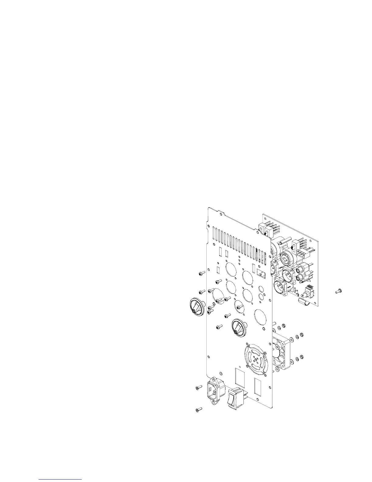
Figure 7.4 - Exploded-view of BOP faceplate assembly
 Loading...


