2
TD-000541 -01-B
Connections and Controls
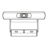
Front Panel
1. STATUS LED –
◦ Green LED
◦ Off indicates the camera is in STANDBY mode,
network streams are off.
◦ On indicates the camera is streaming video over
the network.
◦ Blinking indicates the ID mode is on
2. POWER LED -
◦ Blue LED
◦ On indicates the camera has power applied
◦ Off indicates the camera has no power applied
Rear Panel
1. Label
◦ Model: PTZ-12x72 or PTZ-20x60
◦ MAC Address
◦ Serial Number (on the bottom of the unit)
2. ID Button – Press to identify this piece of
equipment in Q-SYS Designer, and Confi gurator. The
green STATUS LED, on the front panel, blinks when
in ID mode.
3. FACTORY RESET pin-hole – Use a paperclip or
similar object to insert and press and hold the reset
button for 5 seconds. This resets all parameters to
the factory defaults.
4. Kensington™ Lock slot – Security cable not supplied.
5. LAN / POE – Q-SYS Gigabit Ethernet port / CAT5e
or better / RJ45 / connect to the Q-LAN™ network
switch with Power over Ethernet
6. HDMI – Camera output to various video formats setup
by the users through Q-SYS Designer or a Q-SYS UCI
(User Controlled Interface)
NOTE: When a video format is selected,
it is used by both the HDMI and
3G SDI outputs.
7. 3G SDI – Camera output to various video formats
setup by the user. Setup is through Q-SYS Designer
or a Q-SYS UCI
8. SERVICE – No user-accessible functionality.
9. DC 12 V – Connect an external power supply (not included). Supply to be rated at 12 V / 1 A, center-pin positive, outside barrel
negative. Use only a Class 2 / LPS Power Supply.
— Figure 1 —
STATUS POWER
2
1
— Figure 2 —
2134
56789