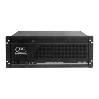
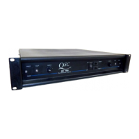
Do you have a question about the QSC USA 400 and is the answer not in the manual?
Warning to reduce risk of electric shock, do not open.
Warning to prevent fire or shock, do not expose to rain or moisture.
Explains the 8-position DIP switch for amplifier characteristics.
Details parallel inputs and stereo/bridge mode configurations.
How DIP switches 3 and 6 enable/disable the limiter for each channel.
How DIP switches 4, 5, 7, 8 control the high-pass filter and cut-off frequency.
Illustrates signal flow for parallel, stereo, and bridged mono operations.
Details the switch for selecting stereo or bridged mono operation.
Safety warnings for high output voltages in bridged mono mode.
Instructions for setting gain controls for bridged mono operation.
How the limiter protects against clipping and reduces signal amplitude.
Describes the Output Averaging™ circuit for short circuit protection.
Explains how the amplifier mutes outputs if heatsink temperature exceeds 90° C.
| Power Output @ 4 Ohms | 200 W |
|---|---|
| RMS Power bridged @ 8 Ohms | 400 W |
| Signal-to-Noise Ratio | >100 dB |
| Damping Factor | >200 |
| Channels | 2 |
| Frequency Response | 20 Hz - 20 kHz |
| Cooling | Convection |
| Dimensions | 19" x 3.5" x 12.25" (48.3 cm x 8.9 cm x 31.1 cm) |