10 11
You may view this DVR using a standard 19” (or larger) VGA monitor or a television. The
former is connected using the VGA port on the back panel while the television utilizes the
BNC “Video Out” port on the back. Your DVR is configured to use the VGA port as the main
display. To use a TV, you will need to press and hold the STOP/ESC, EXIT or VGA/TV button
(depending on model) for approximately 10 seconds until you hear a beep indicating that the
video mode has been switched. A display connected to the other port will not show the menu.
CONNECTIONS AND CONTROLS
CHAPTER 2
ITEM NAME FUNCTION
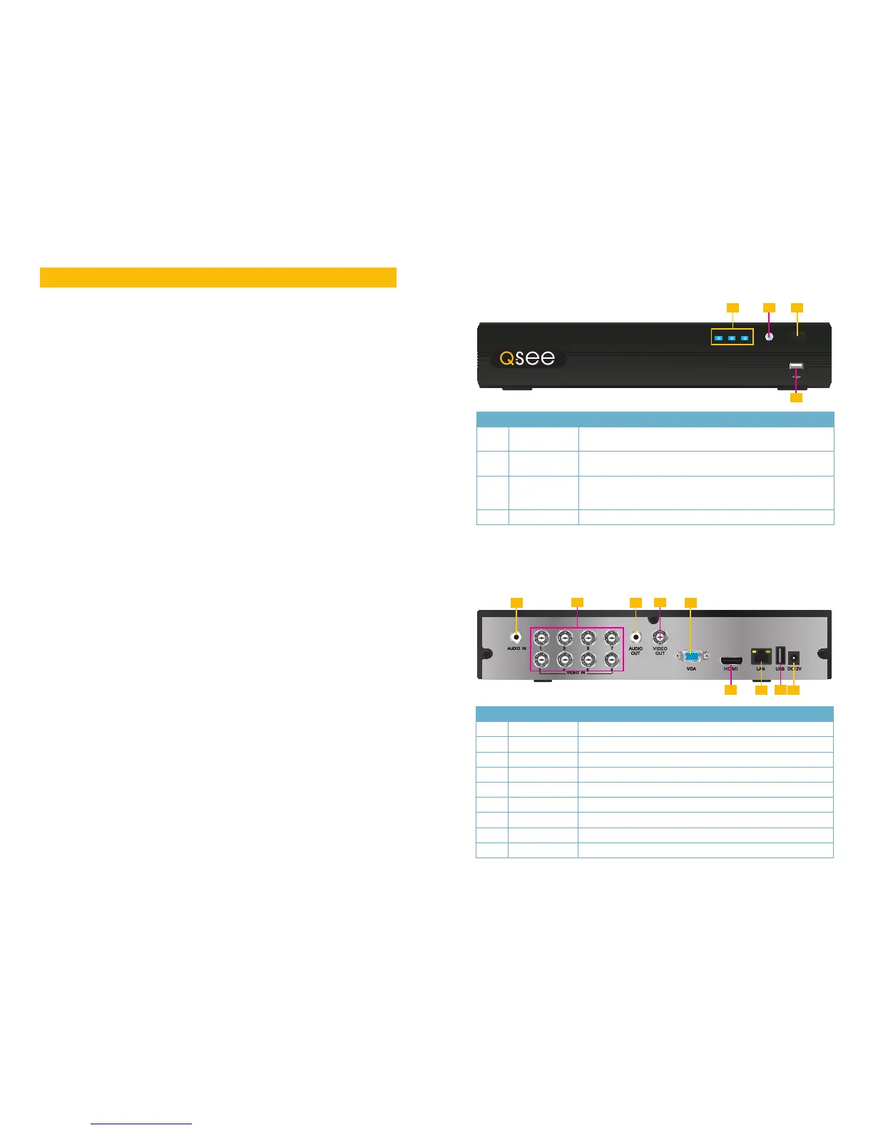
1 INDICATOR
LIGHTS
Shows the recording, network and power status of the DVR.
2 INFRARED
WINDOW
Receives signals from the remote control
3 VIDEO MODE
BUTTON
Press and hold 10 seconds (or until you hear a beep) to switch
video output from the VGA port (default) to the BNC video out
port.
4 USB PORT Used for external USB backup devices.
ITEM NAME FUNCTION
1 AUDIO IN 1 Channel of audio input
2 VIDEO IN Video input from up to 8 cameras
3 AUDIO OUT RCA Audio output for amplified speaker
4 VIDEO OUT BNC connector for TV or monitor
5 VGA PORT VGA output for 19” or larger monitor
6 HDMI HDMI video output
7 LAN Network (ethernet) port
8 USB PORT For the USB mouse
9 DC IN Power input for 12V DC power supply
FRONT PANEL
QT228
REAR PANEL
REC Net Power
TV/VGA
QT228
1 3
4
2
1 3
2
5
7
4
6
9
8
2.1 DVR FUNCTIONS AND CONNECTIONS
 Loading...