1.0 Operating Principle
The Level-Trac LT-310 is a remote level indication system, as described in ASME Section I, PG-60. The system
may also be used as an alarm or trip device.
Discrimination between water and steam is based on the significant difference in resistivity between the two
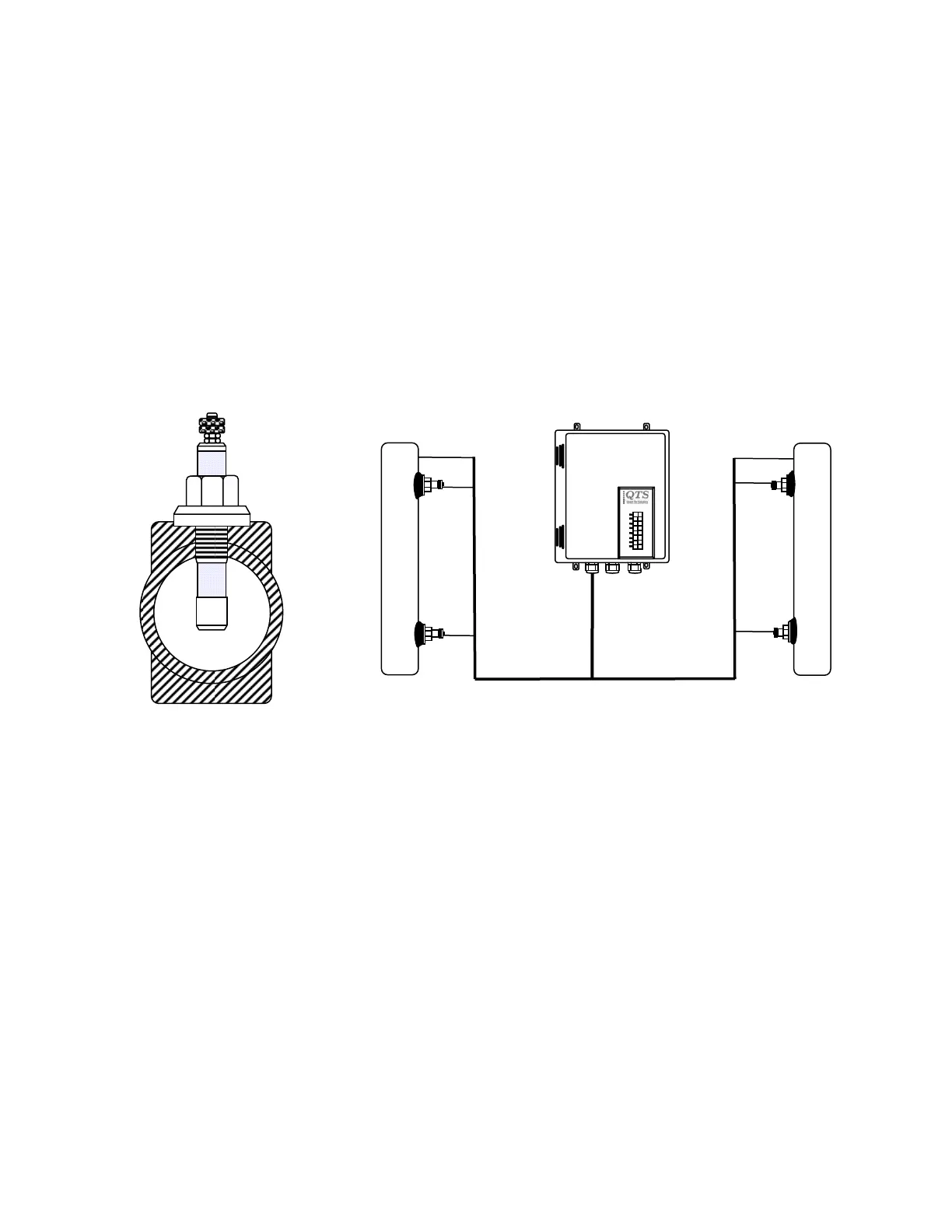
states over the saturation range. The sensing element is a probe with an insulated tip inserted in a probe mani-
fold (Figure 1.1.) If a voltage is applied to the probe tip, conduction occurs between the tip and the inside wall of
the column, resulting in an indication of water. Probe and manifold dimensions are selected to provide a resis-
tance typically less than 100 KΩwhen the probe is immersed in water, as compared to a resistance greater than
5 MΩwhen in contact with steam. An electronic discrimination circuit is arranged to sense whether the Probe
resistance is less than 100 KΩrepresenting water or greater than 5 KΩrepresenting steam.
With probes spaced vertically in a manifold attached to the boiler (Figure 1.1) and with each probe connected to
its own sensing and water/steam indication circuit, a vertical display of Green/Red indicators provides a simula-
tion of water level in the steam drum. Spacing between probes is per customer requirements to cover the visible
range and alarm or trip points.
Typical Probe Manifold
Cross Section
Figure 1.1
2
2.0 System Configuration
Probes are installed in the probe manifold. A length of high temperature wire connects the probes and the mani-
fold to the control unit. The probe manifold itself serves as a common conductor. The presence of water will
complete a circuit between the manifold and the probe tip. The LT-310 is designed with the flexibility to control
six probes from up to six places with complete discrete settings.
Two printed circuit boards contained in a NEMA 4X (IP65) wall mounted enclosure provide up to 6 discrete
water/steam discrimination circuits, LED display, relay alarm/trip outputs, fault detection and terminals for the
connection of a remote display Unit.
To avoid galvanic interaction with the probe and variations in sensing voltage due to changing electrolytic poten-
tials, an alternating voltage source is applied to the probe and the sensing circuit responds only to an alternating
waveform. Two low frequency oscillators are provided for the source voltage; one drives the odd numbered
channels and the other the even numbered channels. The voltage applied to the probe is less than 6 volts, cur-
rent limited to 50 µA, and presents no risk to personnel.
The LT-310 is designed for use with two discrete power sources. In the event of failure of one power source, the
remaining power source will maintain all system functions.
Control Unit
4 probes from two sources
 Loading...