The Common Ground terminals (3 and 4) are common across the entire system, meaning that the common con-
nection for any probe will work for any probe. Each probe holding device should have at least one common
ground connection at minimum. The “B” jump invokes a continuity check of the probe wire, if required. (Units
from the factory will normally have this jump made.)
For unused channels, making the “A” solder jump will cause the display to indicate a Dry state.
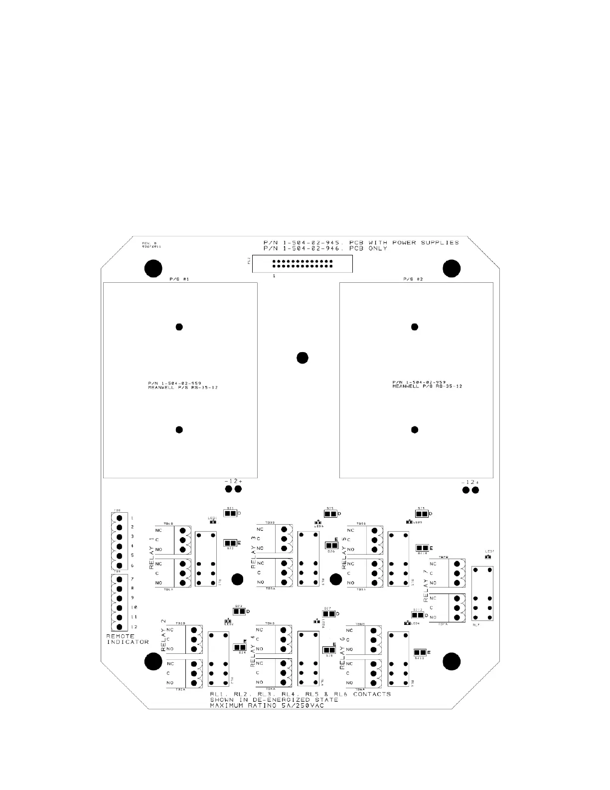
3.4 Wiring Alarm/Trip Relays
Figure 3.4 shows the connection point for relays and remote indicator. Each terminal block is supplied with a
Phoenix Series MSTB plug.
There is an LED located at each relay to indicate the current status of the relay. When illuminated, the corre-
sponding relay is energized. The relays are rated 8A at 250 VAC. Note: If the continuous load is anticipated to
be greater than 5A at 250 VAC, the board traces must be replaced with wire. This is a factory modification.
6
Figure 3.4.1