5
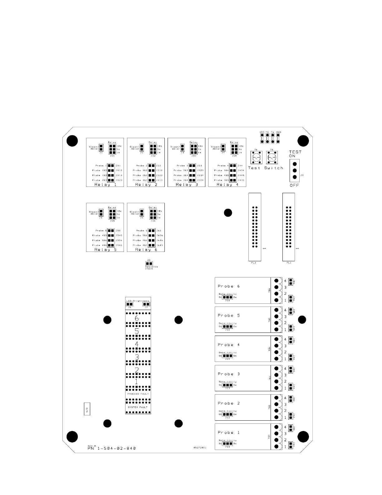
Figure 3.3.1
3.3 Wiring Control Unit-to-Probes
It is recommended that a continuous length of high temperature cable be used to cover the span from the probes
to the LT-310 control unit. Quest-Tec Solutions has a custom fabricated cable, available as an option, in 8, 12,
16 and 25 conductor versions. (The specification for 16 conductor cable is attached as Appendix B to this man-
ual.) 20 AWG, nickel plated copper conductors should be used where elevated temperatures are expected. A
maximum run of no more than 100 feet is recommended. Two conductors are required for each normally Dry
probe, one conductor for each normally Wet probe, and two conductors for system Common.
Figure 3.3.1 shows the terminals provided for wiring the probes. Four terminals are supplied for each probe.
Terminals 1 and 2 are for the probes, terminals 3 and 4 are for the Common Ground. To the right of each termi-
nal block are two sets of solder pad jumps. The “A” jumps tie the two probe wires together, and should be
jumped for all probes that are expected to be wet in the normal state. When “A” is jumped, a single wire can be
used for the probe, either terminal 1 or 2.