4
2.3 Sensitivity
Each probe channel of the LT-310 can be set to one of three sensitivity ranges:
>4 mS/cm²
>2 mS/cm²
>1 mS/cm²
These values are effectively halved by using a shrouded probe. This increases the surface area of the system
common and places the common much closer to the probe sensing element. Sensitivity is rarely an issue, and it
is suggested that the mid-range setting be used initially to evaluate system performance in the actual applica-
tion.
2.4 Test Switches
The LT-310 is supplied with two test switches, that simulate an all Wet or all Dry state. There is an On/Of slide
switch that activates the Red/Green test switches and prevents the corresponding relays from going into alarm
state during a simulation. When the slide switch is in the “On” position, System Fault will be indicated as a re-
minder that the LT-310 is in the simulation mode.
2.5 System Fault
System Fault is indicated by a flashing yellow LED labeled “SF” on the indicator and the activation of RL7.
There are three triggers for System Fault:
1. A failed power supply. If one of the switching power supplies fails, the remaining switching power supply will
power the unit until the fault is corrected.
2. The On/Off slide switch that enables the Red/Green test switches is in the “On” position.
3. When the invoked via solder jumps on the discriminator PCB: out of sequence logic (i.e. Water over Steam).
This is only valid where the probes are installed in a vertical progression respective of water level.
A failed probe insulator will typically cause the probe to be grounded, regardless of whether it is normally Wet or
Dry. Hence, a dry probe with a failed insulator will indicate as Wet. If this occurs with a probe that has a func-
tioning Dry probe below it, the out of sequence logic will declare a System Fault.
Probe cable monitoring is achieved by verifying continuity between two wires to probes that are expected to be
normally Dry. A break in continuity between these two wires will simulate a Wet probe, and cause a System
Fault. For the single wire connection to the normally Wet probes, an open-circuit connection will indicate Dry,
activating the out of sequence Fault Detection circuit.
2.6 Process Fault
Process Fault is indicated by a flashing yellow LED labeled “PF” on the indicator, and is invoked by any channel
that is not in its normal state, wet or dry.
3.0 Installation and Cabling
3.1 Enclosure
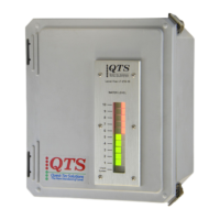
The LT-310 Electronic Unit enclosure is usually located adjacent to the probe manifold. The LT-310 enclosure
should be located to provide clear routing of cables, minimum risk of damage from surrounding plant or activi-
ties and adequate visibility of the display. The standard enclosure is a Stahlin Diamond Shield, Model
DS100806HPL, supplied with mounting foot kit. The instructions for mounting this enclosure are provided as
Appendix A of this manual.
3.2 Main Power Supply
Line, Neutral and Earth Ground are connected directly to the switching power supplies located in the base of the
enclosure. The power requirements are: 100 to 240 VAC ± 10% @ 15VA, 48 - 63 Hz. If two power sources are
not available, install a wire jump to connect the switching power supplies.

 Loading...